Module Operation
www.ti.com
1254
SPNU563A–March 2018
Submit Documentation Feedback
Copyright © 2018, Texas Instruments Incorporated
FlexRay Module
Example of a 8/16/32-bit host access sequence:
• Configure / update n-th message buffer through IBF
• Wait until IBCR.IBSYH is reset
• Write data section to WRDSn
• Write header section to WRHS1,2,3
• Write command mask: write IBCM.STXRH, IBCM.LHSH, IBCM.LDSH
• Demand data transfer to target message buffer: write IBCR.IBRH(6-0)
Configure / update further message buffer through IBF in the same way.
NOTE: Any write access to IBF while IBCR.IBSYH is 1 will set error flag EIR.IIBA in the Error
Interrupt Register to 1. In this case the write access has no effect.
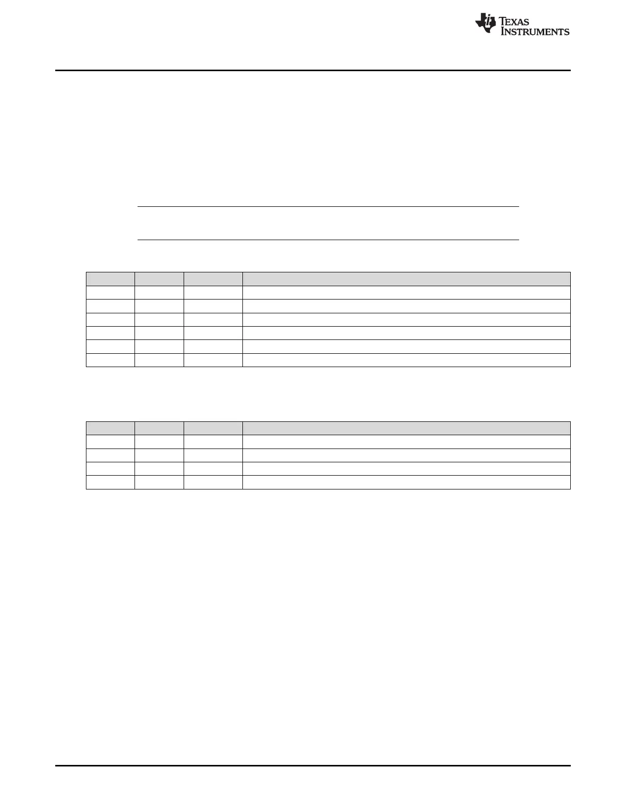
Table 26-12. Assignment of Input Buffer Command Mask Bits
Position Access Bit Function
18 r STXRS Set Transmission Request shadow ongoing or finished
17 r LDSS Load Data Section shadow ongoing or finished
16 r LHSS Load Header Section shadow ongoing or finished
2 r/w STXRH Set Transmission Request Host
1 r/w LDSH Load Data Section Host
0 r/w LHSH Load Header Section Host
Table 26-13. Assignment of Input Buffer Command Request Bits
Position Access Bit Function
31 r IBSYS IBF Busy Shadow, signals ongoing transfer from IBF shadow to message RAM
22-16 r IBRS(6-0) IBF Request Shadow, number of message buffer currently / last updated
15 r IBSYH IBF Busy Host, transfer request pending for message buffer referenced by IBRH(6-0)
6-0 r/w IBRH(6-0) IBF Request Host, number of message buffer to be updated next
26.2.12.2.2 Data Transfer from Message RAM to Output Buffer
To read out a message buffer from the message RAM, the host has to write to the output buffer command
mask and command request register to trigger the data transfer. After a transfer has completed the host
can read the transferred data from the RDDSn, RDHS1,2,3, and MBS.
 Loading...


