Interrupt
Source 1
0
1
CC_int0
CC_int1
Status/Error
Interrupt Enable
Set/Clear
(SIES/EIES, SIER/
EIER
Status/Error
Interrupt Line
Select
(SILS/EILS)
EINT0
EINT1
Source 1
Flag
Interrupt Line
Enable
Interrupt
Source 2
0
1
Status/Error
Interrupt
Register
(SIR/EIR
Interrupt
Line 0
Interrupt
Line 1
Source 2
Flag
Timer 0
Interrupt
Timer 1
Interrupt
CC_tint0
CC_tint1
Module Operation
www.ti.com
1272
SPNU563A–March 2018
Submit Documentation Feedback
Copyright © 2018, Texas Instruments Incorporated
FlexRay Module
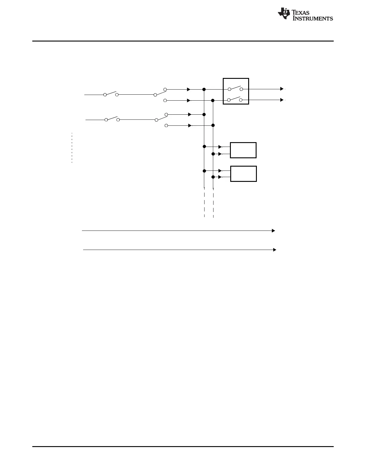
Figure 26-31. Communication Controller (CC) Interrupt Structure
Tracking status and generating interrupts when a status change or an error occurs are two independent
tasks. Independent of an interrupt being enabled, the corresponding status is tracked and indicated by the
Communication Controller. The host has access to the current status and error information by reading the
error interrupt register and the status interrupt register.
The interrupt lines to the host, CC_int0 and CC_int1, are controlled by the enabled interrupts. In addition
each of the two interrupt lines to the host CPU can be enabled / disabled separately by programming bit
EINT0 and EINT1 in the Interrupt Line Enable register.
The two timer interrupts generated by interrupt timer 0 and 1 are available on pins CC_tint0 and CC_tint1.
They can be configured via the timer 0 and timer 1 configuration register.
When a transfer between IBF / OBF and the Message RAM has completed bit SIR.TIBC or SIR.TOBC is
set.

 Loading...


