www.ti.com
FlexRay Module Registers
1415
SPNU563A–March 2018
Submit Documentation Feedback
Copyright © 2018, Texas Instruments Incorporated
FlexRay Module
26.3.2.9.7 Output Buffer Command Request Register (OBCR)
After setting bit REQ to 1 while OBSYS is 0, OBSYS is automatically set to 1, OBRS(6-0) is copied to the
register internal storage, mask bits OBCM.RDSS and OBCM.RHSS are copied to register OBCM internal
storage, and the transfer of the message buffer selected by OBRS(6-0) from the Message RAM to OBF
Shadow is started. When the transfer between the Message RAM and OBF shadow has completed, this is
signaled by setting OBSYS back to 0.
By setting bit VIEW to 1 while OBSYS is 0, OBF Host and OBF shadow are swapped. Additionally mask
bits OBCM.RDSH and OBCM.RHSH are swapped with the register OBCM internal storage to keep them
attached to the respective output buffer transfer. OBRH(6-0) signals the number of the message buffer
currently accessible by the Host.
If bits REQ and VIEW are set to 1 with the same write access while OBSYS is 0, OBSYS is automatically
set to 1 and OBF shadow and OBF host are swapped. Additionally mask bits OBCM.RDSH and
OBCM.RHSH are swapped with the registers internal storage to keep them attached to the respective
output buffer transfer. Afterwards OBRS(6-0) is copied to the register
internal storage, and the transfer of the selected message buffer from the Message RAM to OBF shadow
is started. While the transfer is ongoing the Host can read the message buffer transferred by the previous
transfer from OBF host. When the current transfer between Message RAM and OBF shadow has
completed, this is signaled by setting OBSYS back to 0.
Any write access to OBCR(15-8) while OBSYS is set will cause the error flag IOBA in the Error Interrupt
Register to be set.
In this case the output buffer will not be changed.
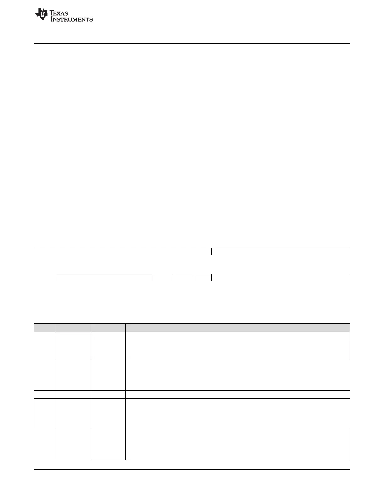
Figure 26-192 and Table 26-165 illustrate this register.
Figure 26-192. Output Buffer Command Mask Register (OBCR) [offset_CC = 714h]
31 23 22 16
Reserved OBRH
R-0 R/W-0
15 14 10 9 8 7 6 0
OBSYS Reserved REQ VIEW Rsvd OBRS
R-0 R-0 R/W-0 R/W-0 R-0 R/W-0
LEGEND: R/W = Read/Write; R = Read only; -n = value after reset; *These bits can be updated in DEFAULT_CONFIG or CONFIG state
only
Table 26-165. Output Buffer Command Mask Register (OBCR) Field Descriptions
Bit Field Value Description
31-23 Reserved 0 Reads return 0. Writes have no effect.
22-16 OBRH 0-7Fh Output buffer request host. Number of message buffer currently accessible by the Host via
RDHS[1..3], MBS, and RDDS[1..64]. By writing VIEW to 1 OBF Shadow and OBF host are
swapped and the transferred message buffer is accessible by the host.
15 OBSYS Output buffer shadow busy. Set to 1 after setting bit REQ. When the transfer between the
message RAM and OBF shadow has completed, OBSYS is set back to 0.
0 No transfer is in progress.
1 Transfer between message RAM and OBF shadow is in progress.
14-10 Reserved 0 Reads return 0. Writes have no effect.
9 REQ Request message RAM Transfer. Requests transfer of message buffer addressed by OBRS from
message RAM to OBF shadow. Only writable while OBSYS = 0.
0 No request.
1 Transfer to OBF shadow is requested.
8 VIEW View shadow buffer. Toggles between OBF shadow and OBF host. Only writable while OBSYS =
0.
0 No action.
1 Swap OBF shadow and OBF.

 Loading...


