www.ti.com
Clocks
147
SPNU563A–March 2018
Submit Documentation Feedback
Copyright © 2018, Texas Instruments Incorporated
Architecture
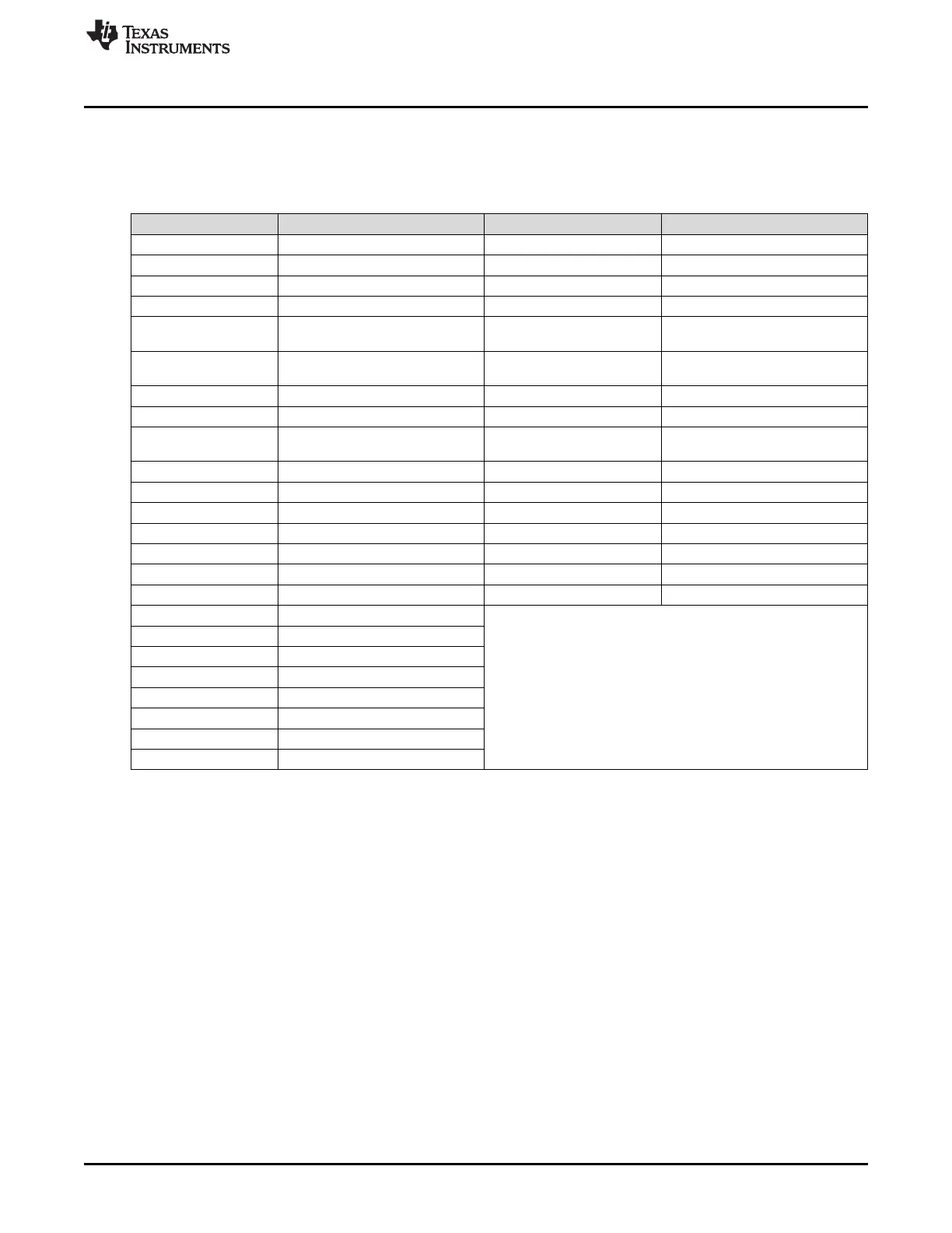
The signal to be brought out on to the ECLK1 terminal is defined by the SEL_ECP_PIN field, and the
signal to be brought out on to the N2HET1[12] terminal is defined by the SEL_GIO_PIN field. The choices
for these selections are defined in Table 2-12.
Table 2-12. Clock Test Mode Options
SEL_ECP_PIN Signal on ECLK SEL_GIO_PIN Signal on N2HET1[12]
00000 Oscillator clock 0000 Oscillator Valid Status
00001 PLL1 clock output 0001 PLL1 Valid Status
00010 Reserved 0010 Reserved
00011 EXTCLKIN1 0011 Reserved
00100
Low-frequency LPO (Low-Power
Oscillator) clock [CLK80K]
0100 Reserved
00101
High-frequency LPO (Low-Power
Oscillator) clock [CLK10M]
0101
HF LPO Clock Output Valid Status
[CLK10M]
00110 PLL2 clock output 0110 PLL2 Valid Status
00111 EXTCLKIN2 0111 Reserved
01000 GCLK1 1000
LF LPO Clock Output Valid Status
[CLK80K]
01001 RTI1 Base 1001 Oscillator Valid Status
01010 Reserved 1010 Oscillator Valid Status
01011 VCLKA1 1011 Oscillator Valid Status
01100 VCLKA2 1100 Oscillator Valid Status
01101 Reserved 1101 Reserved
01110 VCLKA4_DIVR 1110 VCLKA4
01111 Flash HD Pump Oscillator 1111 Oscillator Valid Status
10000 Reserved
10001 HCLK
10010 VCLK
10011 VCLK2
10100 VCLK3
10101-10110 Reserved
10111 EMAC clock output
11000-11111 Reserved

 Loading...


