DCAN Control Registers
www.ti.com
1496
SPNU563A–March 2018
Submit Documentation Feedback
Copyright © 2018, Texas Instruments Incorporated
Controller Area Network (DCAN) Module
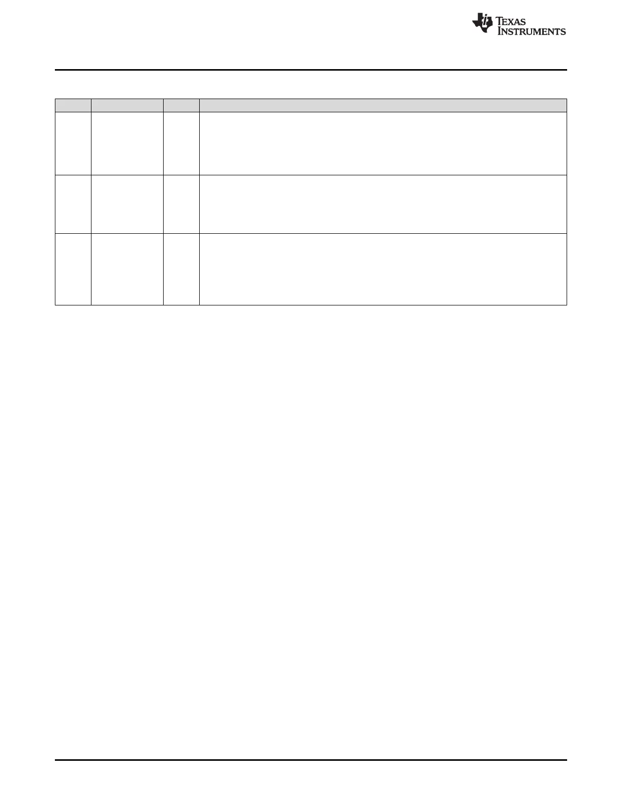
Table 27-35. CAN RX IO Control Register (DCAN RIOC) Field Descriptions (continued)
Bit Field Value Description
2 Dir CAN_RX data direction. This bit controls the direction of the CAN_RX pin when it is configured to
be in GIO mode only (RIOC.Func = 0).
0 The CAN_RX pin is an input.
1 The CAN_RX pin is an output.
Forced to 0, if Init bit of CAN control register is reset.
1 Out CAN_RX data out write. This bit is only active when CAN_RX pin is configured to be in GIO mode
(RIOC.Func = 0) and configured to be an output pin (RIOC.Dir = 1). The value of this bit indicates
the value to be output to the CAN_RX pin.
0 The CAN_RX pin is driven to logic low (0).
1 The CAN_RX pin is at logic high (1).
0 In CAN_RX data in.
0 The CAN_RX pin is at logic low (0).
1 The CAN_RX pin is at logic high (1).
Note: When CAN_RX pin is connected to a CAN transceiver, an external pullup resistor has to be
used to ensure that the CAN bus will not be disturbed (for example, while the DCAN module is
reset).

 Loading...


