www.ti.com
LIN
1653
SPNU563A–March 2018
Submit Documentation Feedback
Copyright © 2018, Texas Instruments Incorporated
Serial Communication Interface (SCI)/ Local Interconnect Network (LIN)
Module
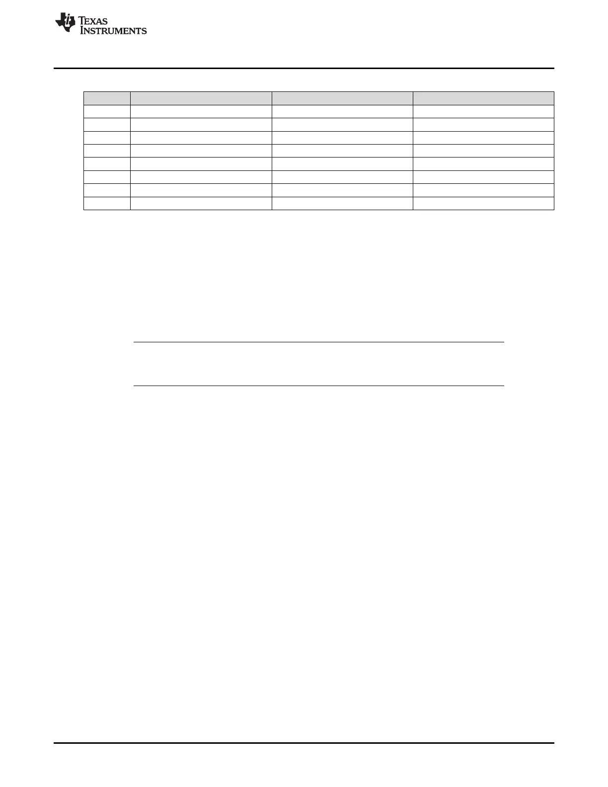
Table 29-8. Timeout Values in T
bit
Units
N T
DATA_FIELD
T
FRAME_MIN
T
FRAME_MAX
1 10 54 76
2 20 64 90
3 30 74 104
4 40 84 118
5 50 94 132
6 60 104 146
7 70 114 160
8 80 124 174
29.3.1.7.2 Bus Idle Detection
The second type of timeout can occur when a node detects an inactive LIN bus: no transitions between
recessive and dominant values are detected on the bus. This happens after a minimum of 4 s (this is
80,000 F
LINCLK
cycles with the fastest bus rate of 20 kbps). If a node detects no activity in the bus as the
TIMEOUT bit is set, then it can be assumed that the LIN bus is in sleep mode. Application software can
use the Timeout flag to determine when the LIN bus is inactive and put the LIN into sleep mode by writing
the POWERDOWN bit.
NOTE: After the timeout was flagged, a SW nRESET should be asserted before entering Low-
Power Mode. This is required to reset the receiver in case that an incomplete frame was on
the bus before the idle period.
29.3.1.7.3 Timeout after Wakeup Signal and Timeout after Three Wakeup Signals
The third and fourth types of timeout are related to the wakeup signal. A node initiating a wakeup should
expect a header from the master within a defined amount of time: timeout after wakeup signal. See
Section 29.4.3 for more details.
29.3.1.8 TXRX Error Detector (TED)
The following sources of error are detected by the TXRX error detector logic (TED). The TED logic
consists of a bit monitor, an ID parity checker, and a checksum error. The following errors are detected:
• Bit errors (BE)
• Physical bus errors (PBE)
• Identifier parity errors (PE)
• Checksum errors (CE)
All of these errors (BE, PBE, PE, CE) are flagged. An interrupt for the flagged errors will be generated if
enabled. A message is valid for both the transmitter and the receiver if there is no error detected until the
end of the frame.

 Loading...


