INT0
INT1
INT2
INT3
INT4
INT5
INT6
INT7
INT8
INT9
Priority Encoder 1
Priority Encoder 0
SCIINTFLR
SCISETINT
SCICLRINT
SCISETINTL
SCICLRL
INT 1
INT 0
SCIINTVECT1
SCIINTVECT0
INT10
INT11
INT12
INT13
INT14
INT15
INT16
www.ti.com
SCI Interrupts
1725
SPNU563A–March 2018
Submit Documentation Feedback
Copyright © 2018, Texas Instruments Incorporated
Serial Communication Interface (SCI) Module
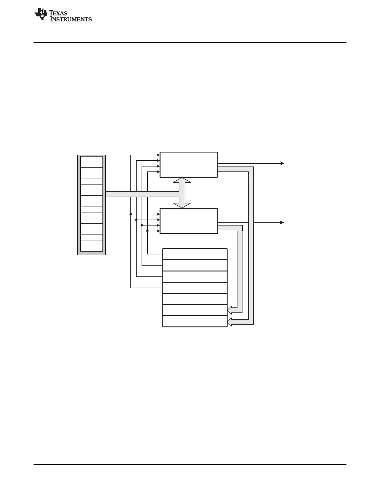
30.3 SCI Interrupts
The SCI module has two interrupt lines, level 0 and level 1, to the vectored interrupt manager (VIM)
module (see Figure 30-6). Two offset registers SCIINTVECT0 and SCIINTVECT1 determine which flag
triggered the interrupt according to the respective priority encoders. Each interrupt condition has a bit to
enable/disable the interrupt in the SCISETINT and SCICLRINT registers, respectively.
Each interrupt also has a bit that can be set as interrupt level 0 (INT0) or as interrupt level 1 (INT1). By
default, interrupts are in interrupt level 0. SCISETINTLVL sets a given interrupt to level1.
SCICLEARINTLVL resets a given interrupt level to the default level 0.
The interrupt vector registers SCIINTVECT0 and SCIINTVECT1 return the vector of the pending interrupt
line INT0 or INT1. If more than one interrupt is pending, the interrupt vector register holds the highest
priority interrupt.
Figure 30-6. General Interrupt Scheme

 Loading...


