APRD
TSCTR
FFFFFFFF
ACMP
0000000C
APWMx
(o/p pin)
On
time
Off−time
Period
1000h
500h
300h
www.ti.com
Application of the APWM Mode
1945
SPNU563A–March 2018
Submit Documentation Feedback
Copyright © 2018, Texas Instruments Incorporated
Enhanced Capture (eCAP) Module
33.4 Application of the APWM Mode
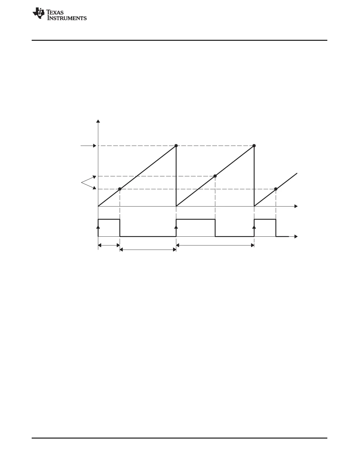
In this section, the eCAP module is configured to operate as a PWM generator. Here a very simple single
channel PWM waveform is generated from output pin APWMx. The PWM polarity is active high, which
means that the compare value (CAP2 reg is now a compare register) represents the on-time (high level) of
the period. Alternatively, if the APWMPOL bit is configured for active low, then the compare value
represents the off-time. Note here values are in hexadecimal (“h”) notation.
33.4.1 Simple PWM Generation (Independent Channel/s)
Figure 33-13. PWM Waveform Details of APWM Mode Operation
33.4.1.1 Code Snippet for APWM Mode
// Code snippet for APWM mode Example 1
// Initialization Time
//=======================
// ECAP module 1 config
ECap1Regs.CAP1 = 0x1000; // Set period value
ECap1Regs.CTRPHS = 0x0; // make phase zero
ECap1Regs.ECCTL2.bit.CAP_APWM = EC_APWM_MODE;
ECap1Regs.ECCTL2.bit.APWMPOL = EC_ACTV_HI; // Active high
ECap1Regs.ECCTL2.bit.SYNCI_EN = EC_DISABLE; // Synch not used
ECap1Regs.ECCTL2.bit.SYNCO_SEL = EC_SYNCO_DIS; // Synch not used
ECap1Regs.ECCTL2.bit.TSCTRSTOP = EC_RUN; // Allow TSCTR to run
// Run Time (Instant 1, e.g. ISR call)
//======================
ECap1Regs.CAP2 = 0x300; // Set Duty cycle i.e. compare value
// Run Time (Instant 2, e.g. another ISR call)
//======================
ECap1Regs.CAP2 = 0x500; // Set Duty cycle i.e. compare value

 Loading...


