Control Registers
www.ti.com
2142
SPNU563A–March 2018
Submit Documentation Feedback
Copyright © 2018, Texas Instruments Incorporated
Data Modification Module (DMM)
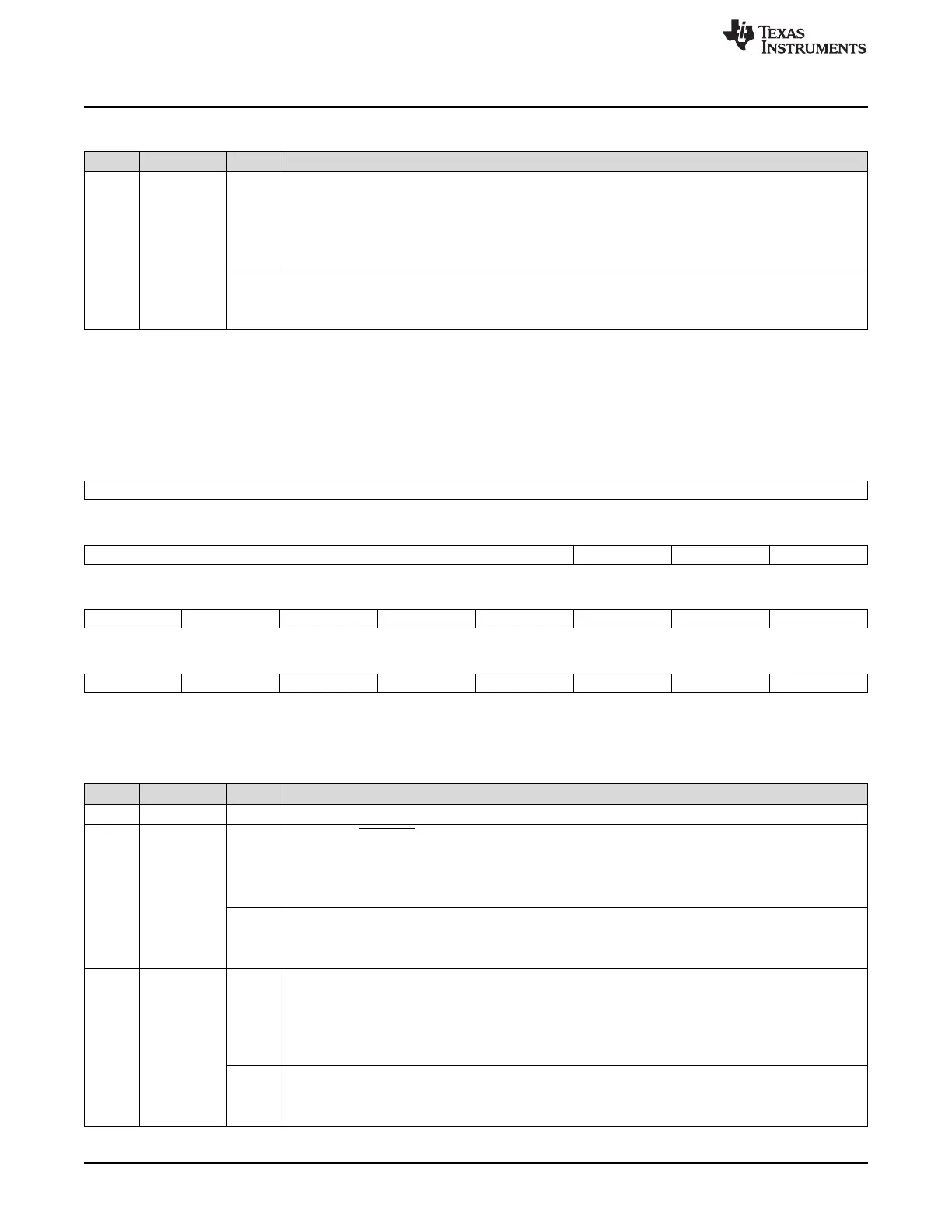
Table 36-22. DMM Pin Control 0 (DMMPC0) Field Descriptions (continued)
Bit Field Value Description
0 SYNCFUNC Functional mode of DMMSYNC pin. This bit defines whether the pin is used in functional mode or in
GIO mode.
User and privilege mode (read):
0 Pin is used in GIO mode.
1 Pin is used in Functional mode.
Privilege mode (write):
0 Pin is used in GIO mode.
1 Pin is used in Functional mode.
36.3.17 DMM Pin Control 1 (DMMPC1)
The bits in this register define the direction of the individual module pins when in GIO mode.
Figure 36-23. DMM Pin Control 1 (DMMPC1) [offset = 70h]
31 24
Reserved
R-0
23 19 18 17 16
Reserved ENADIR DATA15DIR DATA14DIR
R-0 R/WP-0 R/WP-0 R/WP-0
15 14 13 12 11 10 9 8
DATA13DIR DATA12DIR DATA11DIR DATA10DIR DATA9DIR DATA8DIR DATA7DIR DATA6DIR
R/WP-0 R/WP-0 R/WP-0 R/WP-0 R/WP-0 R/WP-0 R/WP-0 R/WP-0
7 6 5 4 3 2 1 0
DATA5DIR DATA4DIR DATA3DIR DATA2DIR DATA1DIR DATA0DIR CLKDIR SYNCDIR
R/WP-0 R/WP-0 R/WP-0 R/WP-0 R/WP-0 R/WP-0 R/WP-0 R/WP-0
LEGEND: R/W = Read/Write; R = Read only; WP = Write in privileged mode only; -n = value after reset
Table 36-23. DMM Pin Control 1 (DMMPC1) Field Descriptions
Bit Field Value Description
31-19 Reserved 0 Reads returns 0. Writes have no effect.
18 ENADIR Direction of DMMENA pin.
User and privilege mode (read):
0 Pin is used as input.
1 Pin is used as output.
Privilege mode (write):
0 Pin is set to input.
1 Pin is set to output.
17-2 DATAxDIR Direction of DMMDATA[x] pin. This bit defines whether the pin is used as input or output in GIO
mode.
User and privilege mode (read):
0 Pin is used as input.
1 Pin is used as output.
Privilege mode (write):
0 Pin is set to input.
1 Pin is set to output.

 Loading...


