RTP Control Registers
www.ti.com
2174
SPNU563A–March 2018
Submit Documentation Feedback
Copyright © 2018, Texas Instruments Incorporated
RAM Trace Port (RTP)
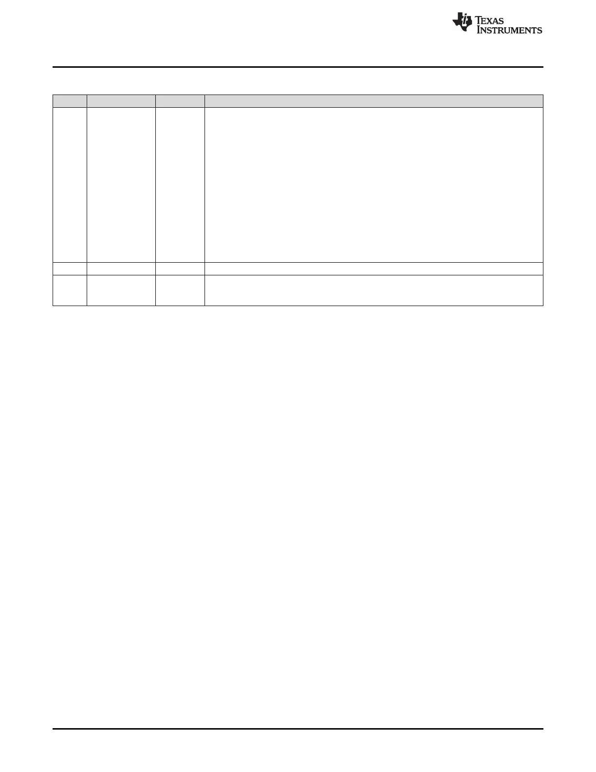
Table 37-15. RTP RAM 3 Trace Region Registers (RTPRAM3REGn) Field Descriptions (continued)
Bit Field Value Description
27-24 BLOCKSIZE These bits define the length of the trace region. Depending on the setting of INV_RGN
(RTPGLBCTRL), accesses inside or outside the region defined by the start address and
blocksize will be traced. If all bits of BLOCKSIZE are 0, the region is disabled and no data will
be captured.
Region size (in bytes):
0 0
1h 256
2h 512
3h 1K
4h 2K
Ah 128K
Bh 256K
Ch-Fh Reserved
23-18 Reserved 0 Reads return 0. Writes have no effect.
17-0 STARTADDR 0-3 FFFFh These bits define the starting address of the address region that should be traced. The start
address has to be a multiple of the block size chosen. If the start address is not a multiple of
the block size, the start of the region will begin at the next lower block size boundary.

 Loading...


