Error Signal
Low-Time
Counter
error_group1
error_group2
error_group3
ERROR
Control
Low-Time
Counter Preload
Memory mapped register interface
Peripheral clock (VCLK)
CPU clock (GCLK)
(
LTCP )
(LTC)
ERROR Pin Enable
Controlled by:
ESMIEPSR1
ESMIEPCR1
ESMIEPSR4
ESMIEPCR4
Device
Output
PIN
ESMEPSR
ESMIEPSR7
ESMIEPCR7
Interrupt Priority
Controlled by:
ESMILSR1
ESMILCR1
ESMILSR4
ESMILCR4
Low-Priority
Interrupt Handling
High-Priority
Interrupt Handling
error_group1
error_group2
Low-Priority Interrupt
High-Priority Interrupt
from Hardware Diagnostics
to VIM Interrupt Controller
Interrupt Enable
Controlled by:
ESMIESR1
ESMIECR1
ESMIESR4
ESMIECR4
ESMIESR7
ESMIECR7
ESMILSR7
ESMILCR7
Overview
www.ti.com
560
SPNU563A–March 2018
Submit Documentation Feedback
Copyright © 2018, Texas Instruments Incorporated
Error Signaling Module (ESM)
Table 16-1. ESM Interrupt and ERROR Pin Behavior
Error Group Interrupt Generated Interrupt Priority ERROR Pin Response Generated
1 configurable interrupt configurable priority configurable output generation
2 interrupt generated high priority output generated
3 no interrupt NA output generated
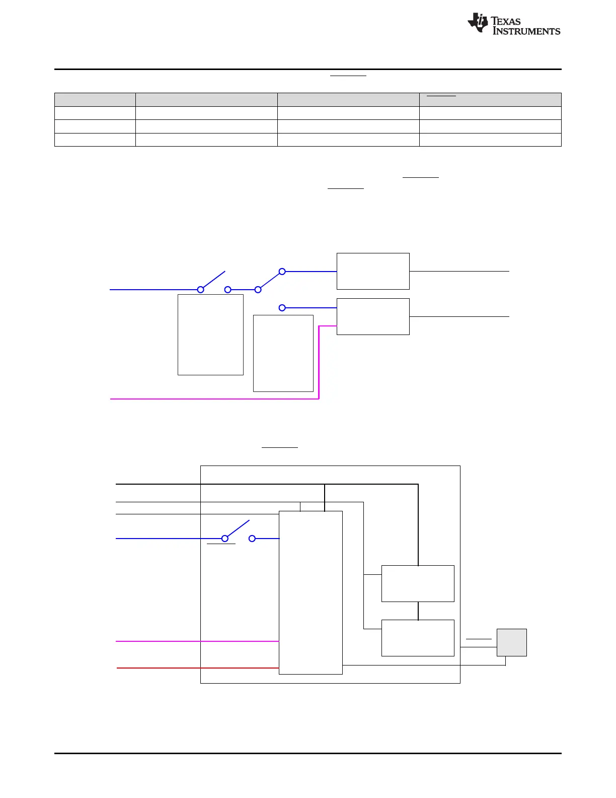
Figure 16-2 and Figure 16-3 show the interrupt response handling and ERROR pin response handling
with register configuration. The total active time of the ERROR pin is controlled by the Low-Time Counter
Preload register (LTCP) and the key register (ESMEPSR) as shown in Figure 16-3. See Section 16.2.2 for
details.
Figure 16-2. Interrupt Response Handling
Figure 16-3. ERROR Pin Response Handling

 Loading...


