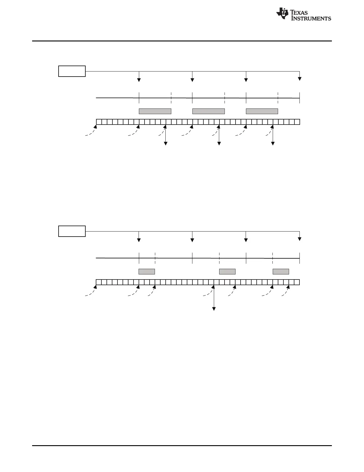
Timer
Time scale
HW DMA req every 10 ms
Data
0 ms 10 ms 20 ms 30 ms
3 ms 15 ms 25 ms
Timeout
Counter
WD
pre-load
BC
pre-load
WD
pre-load
BC
pre-load
WD
pre-load
BC
pre-load
WD
pre-load
timeout
interrupt
WD pre-load = watchdog timeout pre-load (CRC_WDTOPLDx)
BC pre-load = block complete timeout pre-load (CRC_BCTOPLDx)
Note: Timeout interrupt is generated in this example since DMA can not transfer the second block of data within 10ms time
limit and the reason may be that DMA is set up in fixed priority scheme and DMA is serving other higher priority channels
at the time before it can service the timer request.
Timer
Time scale
HW DMA req every 10 ms
Data
0 ms 10 ms 20 ms 30 ms
6 ms 16 ms 26 ms
Timeout
Counter
WD
pre-load
BC
pre-load
WD
pre-load
BC
pre-load
WD
pre-load
BC
pre-load
WD
pre-load
time out
interrup
time out
interrup
time out
interrup
WD pre-load = watchdog timeout pre-load (CRC_WDTOPLDx)
BC pre-load = block complete timeout pre-load (CRC_BCTOPLDx)
Note: Timeout interrupt is generated in this example since each block of data patterns are compressed in 6 ms and this is
out of the 4ms time frame.
Module Operation
www.ti.com
636
SPNU563A–March 2018
Submit Documentation Feedback
Copyright © 2018, Texas Instruments Incorporated
Cyclic Redundancy Check (CRC) Controller Module
Figure 18-7. Timeout Example 2
Figure 18-8. Timeout Example 3

 Loading...


