Start
Tdischarge
Vreflo
Sampling time
Tsamp
ADINx
Sample cap discharge time
Conversion of last value sampled
www.ti.com
Basic Operation
877
SPNU563A–March 2018
Submit Documentation Feedback
Copyright © 2018, Texas Instruments Incorporated
Analog To Digital Converter (ADC) Module
22.2.6.3.2 Enhanced Power-Down Mode
A bit in the ADC operating mode control register, IDLE_PWRDN (ADOPMODECR.4) enables the
enhanced power-down mode of the ADC.
Once this bit is set, the ADC module will power down the ADC core whenever there are no more ongoing
or pending ADC conversions. The ADC core will be powered down regardless of the state of the
POWERDOWN bit (ADOPMODECR.3).
The ADC module releases the ADC core from power down mode as soon as a new conversion is
requested. The ADC logic state machine then has to wait for at least t
d(PU-ADV)
(see the device data sheet
for actual value) before starting a new conversion. The IDLE_PWRDN bit will remain set at all times. The
logic state machine can use this bit to determine that it needs to wait for a programmable number of VCLK
cycles before it allows the input channel to be sampled. This time is configured by the ADC Power Up
Delay Control register (ADPWRUPDLYCTRL).
If IDLE_PWRDN is not set, the ADC module does not wait for any additional delay before sampling the
input channel and the application software has to take account of this required delay.
22.2.6.3.3 Managing Clocks to the ADC Module
The clock to the ADC module can be turned off via the appropriate Peripheral Central Resource (PCR)
controller PSPWRDNSET register (check the specific device datasheet to identify the register and the bit
to be set). If a conversion is ongoing when this bit is set, the ADC module will wait until the current
conversion completes before allowing the ADC module clock to be stopped.
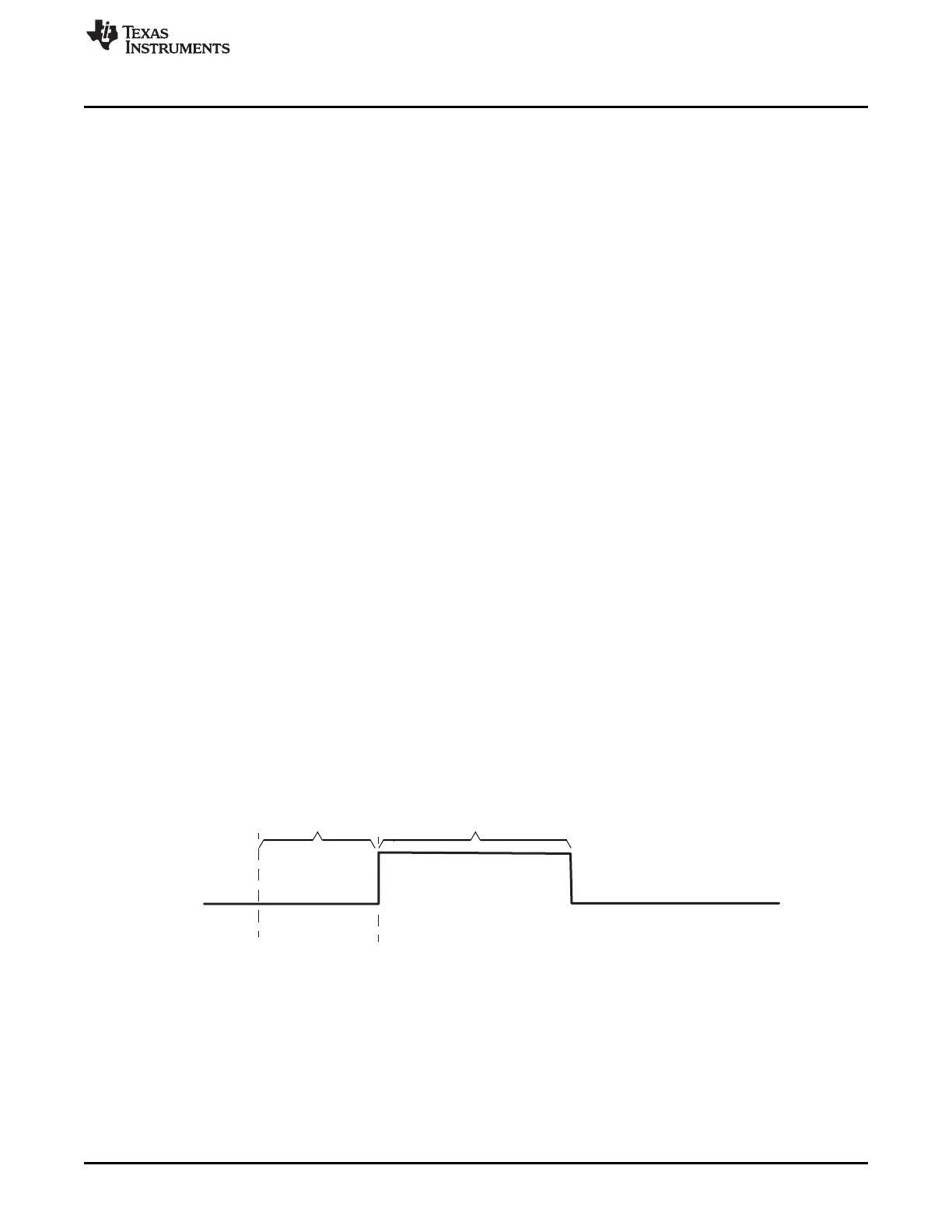
22.2.6.4 ADC Sample Capacitor Discharge Mode
This mode allows the charge on the ADC core’s internal sampling capacitor to be discharged before
starting the sampling phase of the next channel.
The ADC Sample Cap Discharge Mode is enabled by setting the SAMP_DIS_EN bit of the group’s
ADSAMPDISEN register. A discharge period for the sampling capacitor is added before the sampling
period for each channel as shown in Figure 22-17. The duration of this discharge period is configurable via
the corresponding group’s_SAMP_DIS_CYC field in the ADSAMPDISEN register. The discharge time is
specified in terms of number of ADCLK cycles.
During the sample capacitor discharge period, the V
REFLO
reference voltage is connected to the input
voltage terminal of the ADC core. This allows any charge collected on the sampling capacitor from the
previous conversion to be discharged to ground. The V
REFLO
reference voltage is usually connected to
ground.
Figure 22-17. Timing for Sample Capacitor Discharge Mode

 Loading...


