÷
ø
ö
ç
è
æ
·=
M
N
TT
fere n ceR eIn pu t
Instruction Set
www.ti.com
1118
SPNU563A–March 2018
Submit Documentation Feedback
Copyright © 2018, Texas Instruments Incorporated
High-End Timer (N2HET) Module
23.6.3.19 RCNT (Ratio Count)
Syntax RCNT {
[brk={OFF | ON}]
[next={label | 9-bit unsigned integer}]
[control={OFF | ON}]
divisor={25-bit unsigned integer}
[data={25-bit unsigned integer]
}
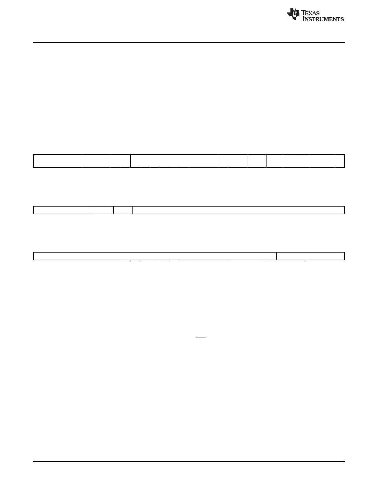
Figure 23-174. RCNT Program Field (P31:P0)
31 26 25 23 22 21 13 12 9 8 7 6 5 4 3 1 0
0 Reserved BRK Next program address 1010 Res. 00 Step
width
Res. 1
6 3 1 9 4 1 2 2 3 1
Figure 23-175. RCNT Control Field (C31:C0)
31 27 26 25 24 0
Reserved Control Res. Divisor
5 1 1 25
Figure 23-176. RCNT Data Field (D31:D0)
31 7 6 0
Data Reserved
25 7
Cycles Two Cycles (One Cycle if T=0)
Register modified None
Description RCNT is used with other instructions to convert an input period measurement
T
Input
to the form of (Equation 31) where the input period is expressed as a
fraction of a reference period T
Reference
.
(31)
RCNT computes the numerator N of (Equation 31). The denominator M of
(Equation 31) is a constant that is of interest. For example, choosing M = 100
allows the input period to be expressed as a percentage (%) of the reference
period. Note that if T
Input
> T
Reference
, then RCNT will return N > M ; which would
be correct if, for example, the input pulse period is 110% of the reference
pulse period.
RCNT expects that register T is loaded with the value of T
Reference
. The input
period T
Input
is determined by counting the number of loop resolution periods
between edges on the input pin. This information is conveyed through the Z
flag from a PCNT instruction that precedes the RCNT instruction.
The divisor field of the RCNT instruction should be chosen as:
Divisor = M · lr , where M is the desired denominator from
(Equation 31) and lr is the loop resolution prescale value.

 Loading...


