Module Operation
www.ti.com
1244
SPNU563A–March 2018
Submit Documentation Feedback
Copyright © 2018, Texas Instruments Incorporated
FlexRay Module
NOTE: For the FIFO the acceptance filter is configured by the FIFO Rejection Filter and the FIFO
Rejection Filter mask.
A message will be transmitted in the time slot corresponding to the configured frame ID on the configured
channel(s). If cycle counter filtering is enabled the configured cycle filter value must also match.
26.2.8.1 Slot Counter Filtering
Every transmit and receive buffer contains a frame ID stored in the header section. This frame ID is
compared against the current slot counter value in order to assign receive and transmit buffers to the
corresponding slot.
If two or more message buffers are configured with the same frame ID and channel ID, and if they have a
matching cycle counter filter value for the same slot, then the message buffer with the lowest message
buffer number is used.
26.2.8.2 Cycle Counter Filtering
Cycle counter filtering is based on the notion of a cycle set. For filtering purposes, a match is detected if
any one of the elements of the cycle set is matched. The cycle set is defined by the cycle code field in the
header section 1 of each message buffer.
If message buffer 0 or 1 is configured to hold the startup / sync frame or the single slot frame by bits
TXST, TXSY, and TSM of SUC Configuration Register 1, cycle counter filtering for message buffer 0 or 1
respectively shall be disabled.
NOTE: Sharing of a static time slot by cycle counter filtering between different nodes of a FlexRay
network is not allowed.
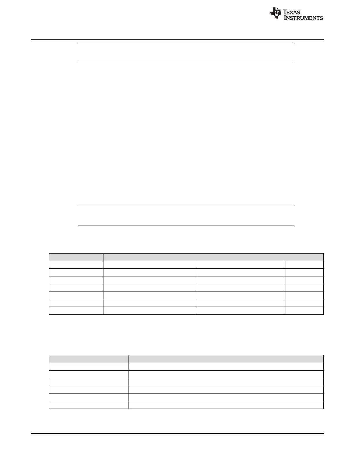
The set of cycle numbers belonging to a cycle set is determined as described in Table 26-8.
Table 26-8. Definition of Cycle Set
Cycle Code Matching Cycle Counter Values
0b000000x All cycles
0b000001c Every second cycle at (cycle count)mod2 = c
0b00001cc Every fourth cycle at (cycle count)mod4 = cc
0b0001ccc Every eighth cycle at (cycle count)mod8 = ccc
0b001cccc Every sixteenth cycle at (cycle count)mod16 = cccc
0b01ccccc Every thirty-second cycle at (cycle count)mod32 = ccccc
0b1cccccc Every sixty-fourth cycle at (cycle count)mod64 = cccccc
Table 26-9 gives some examples for valid cycle sets to be used for cycle counter filtering.
Table 26-9. Examples for Valid Cycle Sets
Cycle Code Matching Cycle Counter Values
0b0000011 1-3-5-7- …. -63 ↵
0b0000100 0-4-8-12- …. -60 ↵
0b0001110 6-14-22-30- …. -62 ↵
0b0011000 8-24-40-56 ↵
0b0100011 3-35 ↵
0b1001001 9 ↵

 Loading...


