• Transfer Configuration RAM (TCR)
• Message RAM
• Transient Buffer RAM A
• Transient Buffer RAM B
• Input Buffer RAM
• Input Buffer Shadow RAM
• Output Buffer RAM
• Output Buffer Shadow RAM
SBE correction on
SBE correction off
SBEL(3-0)
(ECC_CTRL)
FlexRay RAMs
PERR flag
Parity/ECC failure
SBE failure
SBE flag
EIR
ECC failure
SBE failure
PE flag
SE flag
TEIF
faulty frame indication
FMB(6-0)
(MHDS)
faulty RAM location
FRL(10-0)
(SBESTAT)
faulty address indication
ADR(8-0)
(PEADR)
ADR(8-0)
(TSBESTAT)
faulty address indication
UCRE
(EIES/R)
UCREL
(EILS)
CC_int0
CC_int1
TU_UCT_err
E-Ray
Transfer Unit
Parity check
ECC check
TCR ECC off
TCR ECC on
PEL(3-0)
(GCS/R)
closed, if
TCR ECC is on
SBESTAT
TSBESTAT
TU_SBE_err
SBE_EVT_EN(3-0)
(ECC_CTRL)
CC_PERR_err
CC_SBE_err
www.ti.com
Module Operation
1263
SPNU563A–March 2018
Submit Documentation Feedback
Copyright © 2018, Texas Instruments Incorporated
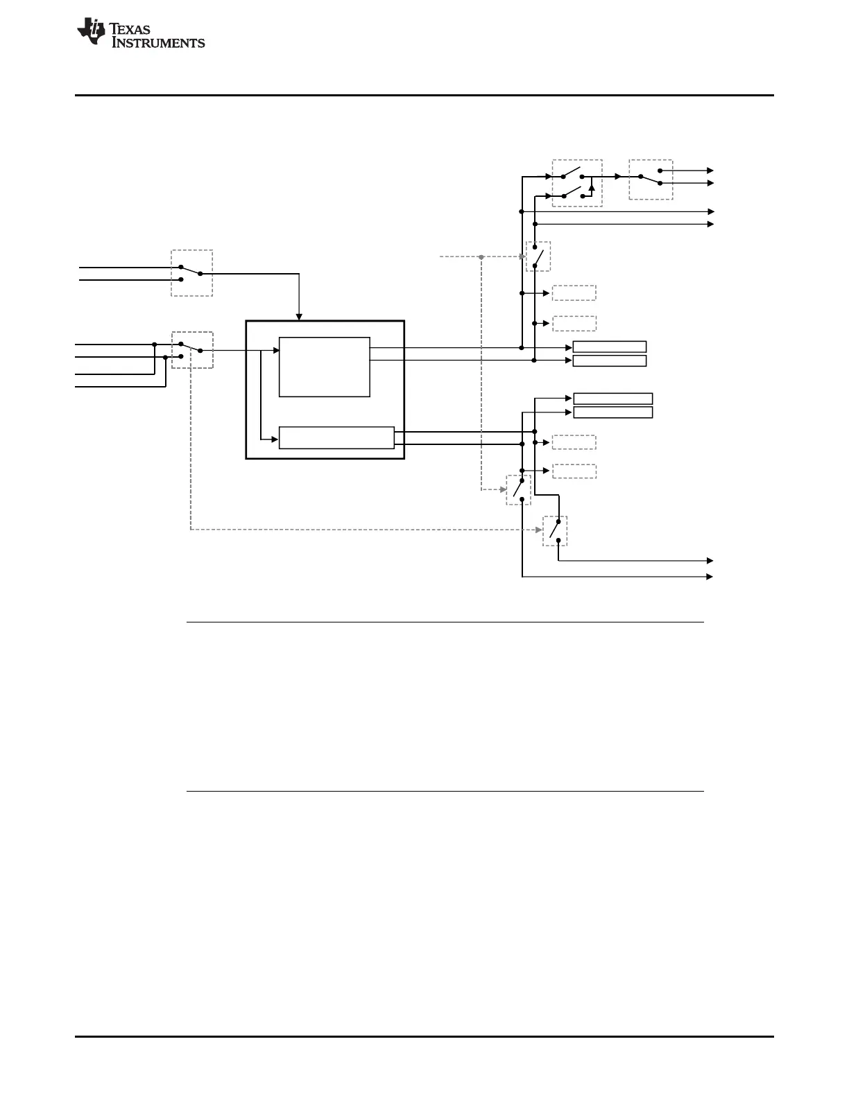
FlexRay Module
Figure 26-26. Parity/ECC Structure
NOTE: There is no parity protection for FlexRay RAM blocks.
For the seven RAM blocks of the Communication Controller portion (message RAM, 2
transient buffer RAMs, 2 input buffer RAMs and 2 output buffer RAMs), ECC protection is
added, which can be selected by the ECC lock bits (PEL(3-0)). ECC protection can not be
switched off completely. For the TCR of the Transfer Unit, actually the ECC multi-bit error
generation will be switched on and off by the ECC lock bits, the ECC generation itself
remains always on.
ECC should be activated before initializing all RAMs by the CLEAR_RAMS command and
should not be switched off during FlexRay usage.
The following paragraphs describe the protection for the Communication Controller related RAM blocks.
For details about the protection of the Transfer Configuration RAM (TCR) of the Transfer Unit, see
Section 26.2.1.1.2.1.
All the Communication Controller related RAM blocks have an ECC generator and an ECC checker
attached as shown in Figure 26-27. When data is written to a RAM block, the local ECC generator
generates the corresponding ECC information.
The ECC protection supports single-bit error correction and double-bit error detection mechanism
(SECDED). The ECC information is stored together with the corresponding data word.
The ECC is checked each time a data word is read from any of the RAM blocks. The module internal data
buses have a width of 32 bits. If an ECC multi-bit error is detected, the PERR error flag is set in the error
interrupt register (EIR). Additionally, the correction of an ECC single-bit error will be indicated by the SBE
flag in the Single-Bit Error Status Register (SBESTAT).

 Loading...


