FlexRay Module Registers
www.ti.com
1338
SPNU563A–March 2018
Submit Documentation Feedback
Copyright © 2018, Texas Instruments Incorporated
FlexRay Module
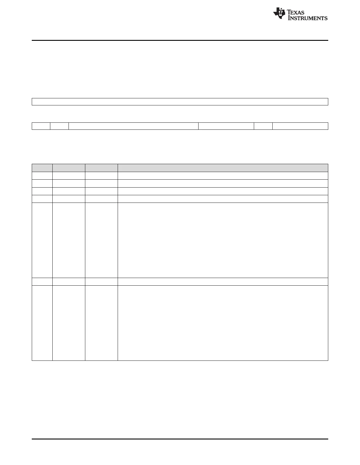
26.3.2.1.6 Test Register 2 (TEST2)
Test register 2 holds all bits required for RAM test of the embedded RAM blocks of the communication
controller. Write access to this register is only possible when bit WRTEN in the test register 1 is set.
Figure 26-114 and Table 26-94 illustrate this register.
Figure 26-114. Test Register 2 (TEST2) [offset_CC = 14h]
31 16
Reserved
R-0
15 14 13 7 6 4 3 1 0
RDPB WRPB Reserved SSEL Rsvd RS
R-0 R/W-0 R-0 R/W-0 R-0 R/W-0
LEGEND: R/W = Read/Write; R = Read only; -n = value after reset
Table 26-94. Test Register 2 (TEST2) Field Descriptions
Bit Field Value Description
31-16 Reserved 0 Reads return 0. Writes have no effect.
15 RDPB 0-1 When ECC mode is enabled, this bit is always read as 0.
14 WRPB 0-1 When ECC mode is enabled, this bit has no effect.
13-7 Reserved 0 Reads return 0. Writes have no effect.
6-4 SSEL Segment select. To enable access to the complete message RAM (8192 byte addresses) the
message RAM is segmented.
0 Access to RAM bytes 0000h to 03FFh is enabled.
1h Access to RAM bytes 0400h to 07FFh is enabled.
2h Access to RAM bytes 0800h to 0BFFh is enabled.
3h Access to RAM bytes 0C00h to 0FFFh is enabled.
4h Access to RAM bytes 1000h to 13FFh is enabled.
5h Access to RAM bytes 1400h to 17FFh is enabled.
6h Access to RAM bytes 1800h to 1BFFh is enabled.
7h Access to RAM bytes 1C00h to 1FFFh is enabled.
3 Reserved 0 Reads return 0. Writes have no effect.
2-0 RS RAM select. In RAM test mode, the RAM blocks selected by RS are mapped to module address
400h to 7FFh (1024 byte addresses).
0 Input buffer RAM 1
1h Input buffer RAM 2
2h Output buffer RAM 1
3h Output buffer RAM 2
4h Transient buffer RAM A
5h Transient buffer RAM B
6h Message RAM
7h Reserved

 Loading...


