www.ti.com
FlexRay Module Registers
1365
SPNU563A–March 2018
Submit Documentation Feedback
Copyright © 2018, Texas Instruments Incorporated
FlexRay Module
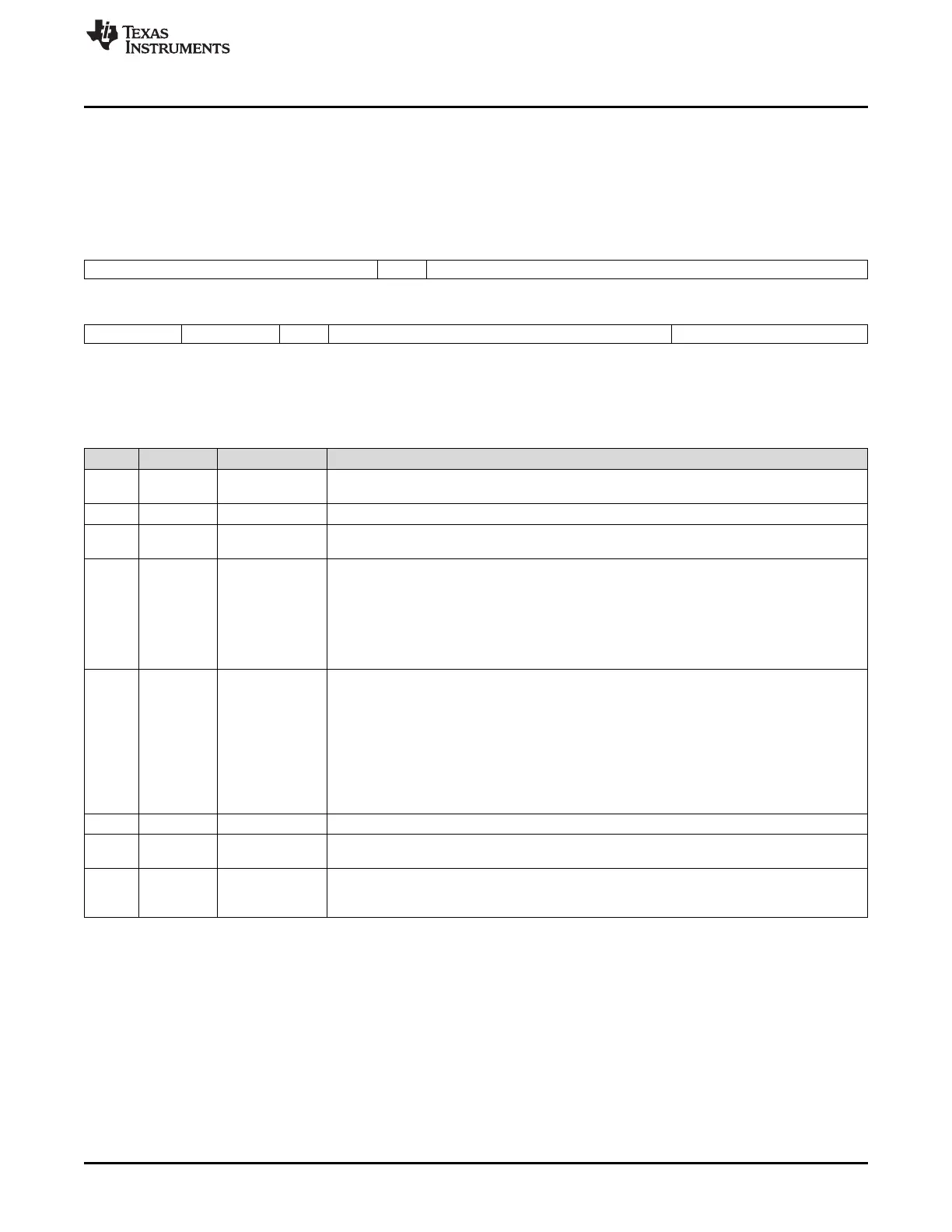
26.3.2.3.5 PRT Configuration Register 1 (PRTC1)
The communication controller accepts modifications of the register in DEFAULT_CONFIG or CONFIG
state only.
Figure 26-132 and Table 26-111 illustrate this register.
Figure 26-132. PRT Configuration Register 1 (PRTC1) [offset_CC = 90h]
31 26 25 24 16
RPW* Rsvd RXW*
R/W-2h R-0 R/W-4Ch
15 14 13 12 11 10 4 3 0
BRP* SSP* Rsvd CASM* TSST*
R/W-0 R/W-0 R-0 R/W-23h R/W-3h
LEGEND: R/W = Read/Write; R = Read only; -n = value after reset; *These bits can be updated in DEFAULT_CONFIG or CONFIG state
only
Table 26-111. PRT Configuration Register 1 (PRTC1) Field Descriptions
Bit Field Value Description
31-26 RWP 2h-3Fh Repetition of transmission wakeup pattern. These bits configure the number of repetitions
(sequences) of the transmission wakeup symbol.
25 Reserved 0 Reads return 0. Writes have no effect.
24-16 RXW 4Ch-12Dh Wakeup symbol receive window length. Configures the number of bit times used by the node to
test the duration of the received wakeup pattern. Must be identical in all nodes of a cluster.
15-14 BRP Baud rate prescaler. These bits configure the baud rate on the FlexRay bus. The baud rates
listed below are valid with a sample clock of 80 MHz. One bit time always consists of 8 samples
independent of the configured baud rate.
0 10 Mbit/s (Sample Clock Period = 12.5ns; 1 µT = 25ns; Samples per µT = 2)
1h 5 Mbit/s (Sample Clock Period = 25ns; 1 µT = 25ns; Samples per µT = 1)
2h-3h 2.5 Mbit/s (Sample Clock Period = 50ns; 1 µT = 50ns; Samples per µT = 1)
13-12 SPP Strobe Point Position. Defines the sample count value for strobing. The strobed bit value is set
to the voted value when the sample count is incremented to the value configured by SPP.
Note: The current revision 2.1 of the FlexRay protocol requires that SPP = 00. The
alternate strobe point positions could be used to compensate for asymmetries in the
physical layer.
0, 3h Sample 5 (default)
1h Sample 4
2h Sample 6
11 Reserved 0 Reads return 0. Writes have no effect.
10-4 CASM 43h-63h bit times Collision avoidance symbol max (in bit times). These bits configure the upper limit of the
acceptance window for a collision avoidance symbol (CAS). CASM6 is always 1.
3-0 TSST 3h-Fh bit times Transmission start sequence transmitter (in bit times). These bits configure the duration of the
transmission start sequence (TSS) in terms of bit times (1 bit time = 4 µT = 100ns @ 10Mbps).
Must be identical in all nodes of a cluster.

 Loading...


