www.ti.com
FlexRay Module Registers
1367
SPNU563A–March 2018
Submit Documentation Feedback
Copyright © 2018, Texas Instruments Incorporated
FlexRay Module
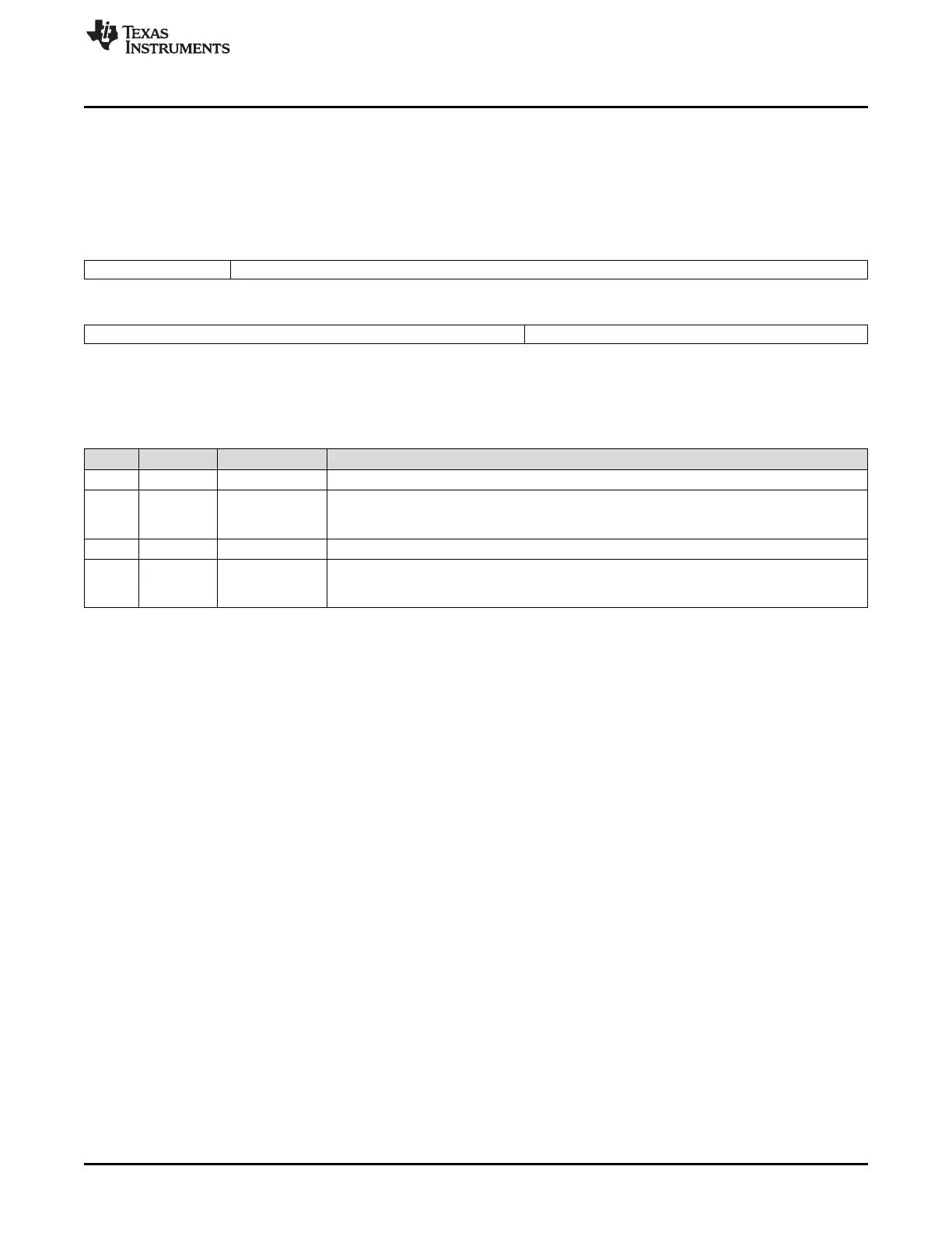
26.3.2.3.7 MHD Configuration Register (MHDC)
The communication controller accepts modifications of the register in DEFAULT_CONFIG or CONFIG
state only.
Figure 26-134 and Table 26-113 illustrate this register.
Figure 26-134. MHD Configuration Register (MHDC) [offset_CC = 98h]
31 29 28 16
Reserved SLT*
R-0 R/W-2h
15 7 6 0
Reserved SFDL*
R-0 R/W-0
LEGEND: R/W = Read/Write; R = Read only; -n = value after reset; *These bits can be updated in DEFAULT_CONFIG or CONFIG state
only
Table 26-113. MHD Configuration Register (MHDC) Field Descriptions
Bit Field Value Description
31-29 Reserved 0 Reads return 0. Writes have no effect.
28-16 SLT 0-1F2Dh
minislots
Start of latest transmit (in minislots). These bits configure the maximum minislot value allowed
before inhibiting new frame transmissions in the Dynamic Segment of the cycle. There is no
transmission in dynamic segment if SLT is cleared to 0.
15-8 Reserved 0 Reads return 0. Writes have no effect.
7-0 SFDL 0-7Fh Static frame data length. These bits configure the cluster-wide payload length for all frames sent
in the static segment in double bytes. The payload length must be identical in all nodes of a
cluster.

 Loading...


