www.ti.com
FlexRay Module Registers
1373
SPNU563A–March 2018
Submit Documentation Feedback
Copyright © 2018, Texas Instruments Incorporated
FlexRay Module
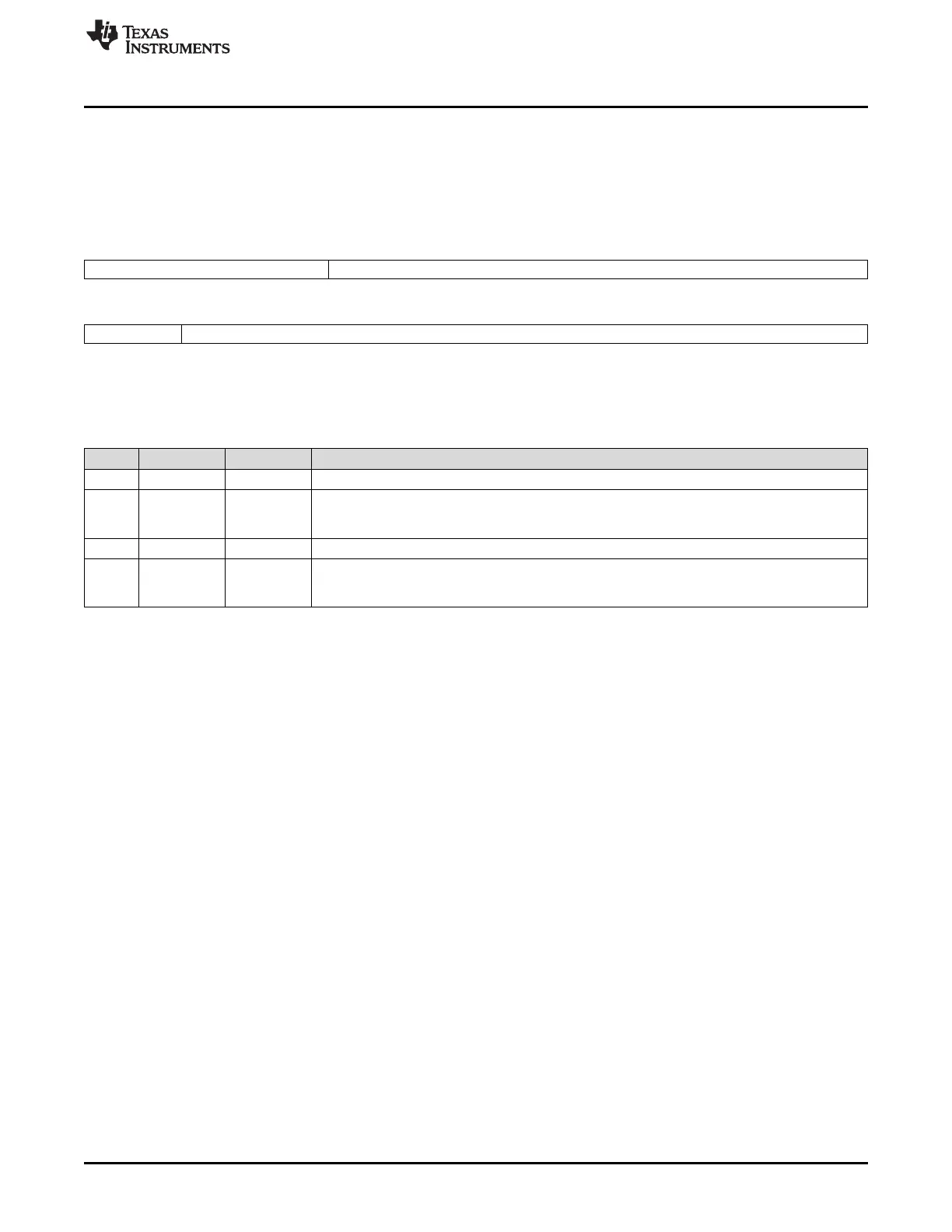
26.3.2.3.17 GTU Configuration Register 10 (GTUC10)
The communication controller accepts modifications of the register in DEFAULT_CONFIG or CONFIG
state only.
Figure 26-144 and Table 26-123 illustrate this register.
Figure 26-144. GTU Configuration Register 10 (GTUC10) [offset_CC = C4h]
31 27 26 16
Reserved MRC*
R-0 R/W-2h
15 14 13 0
Reserved MOC*
R-0 R/W-5h
LEGEND: R/W = Read/Write; R = Read only; -n = value after reset; *These bits can be updated in DEFAULT_CONFIG or CONFIG state
only
Table 26-123. GTU Configuration Register 10 (GTUC10) Field Descriptions
Bit Field Value Description
31-27 Reserved 0 Reads return 0. Writes have no effect.
26-16 MRC 2h-783h µT Maximum rate correction (in microticks). Holds the maximum permitted rate correction value to be
applied by the internal clock synchronization algorithm. The communication controller checks the
internal rate correction value against the maximum rate correction value (absolute value).
15-14 Reserved 0 Reads return 0. Writes have no effect.
13-0 MOC 5h-3BA2h µT Maximum offset correction (in microticks). Holds the maximum permitted offset correction value to
be applied by the internal clock synchronization algorithm (absolute value). The communication
controller checks the internal offset correction value against the maximum offset correction value.

 Loading...


