www.ti.com
FlexRay Module Registers
1387
SPNU563A–March 2018
Submit Documentation Feedback
Copyright © 2018, Texas Instruments Incorporated
FlexRay Module
26.3.2.5 Message Buffer Control Registers
26.3.2.5.1 Message RAM Configuration (MRC)
The message RAM Configuration register defines the number of message buffers assigned to the static
segment, dynamic segment, and FIFO. The register can be written during DEFAULT_CONFIG or CONFIG
state only.
Figure 26-158 and Table 26-137 illustrate this register.
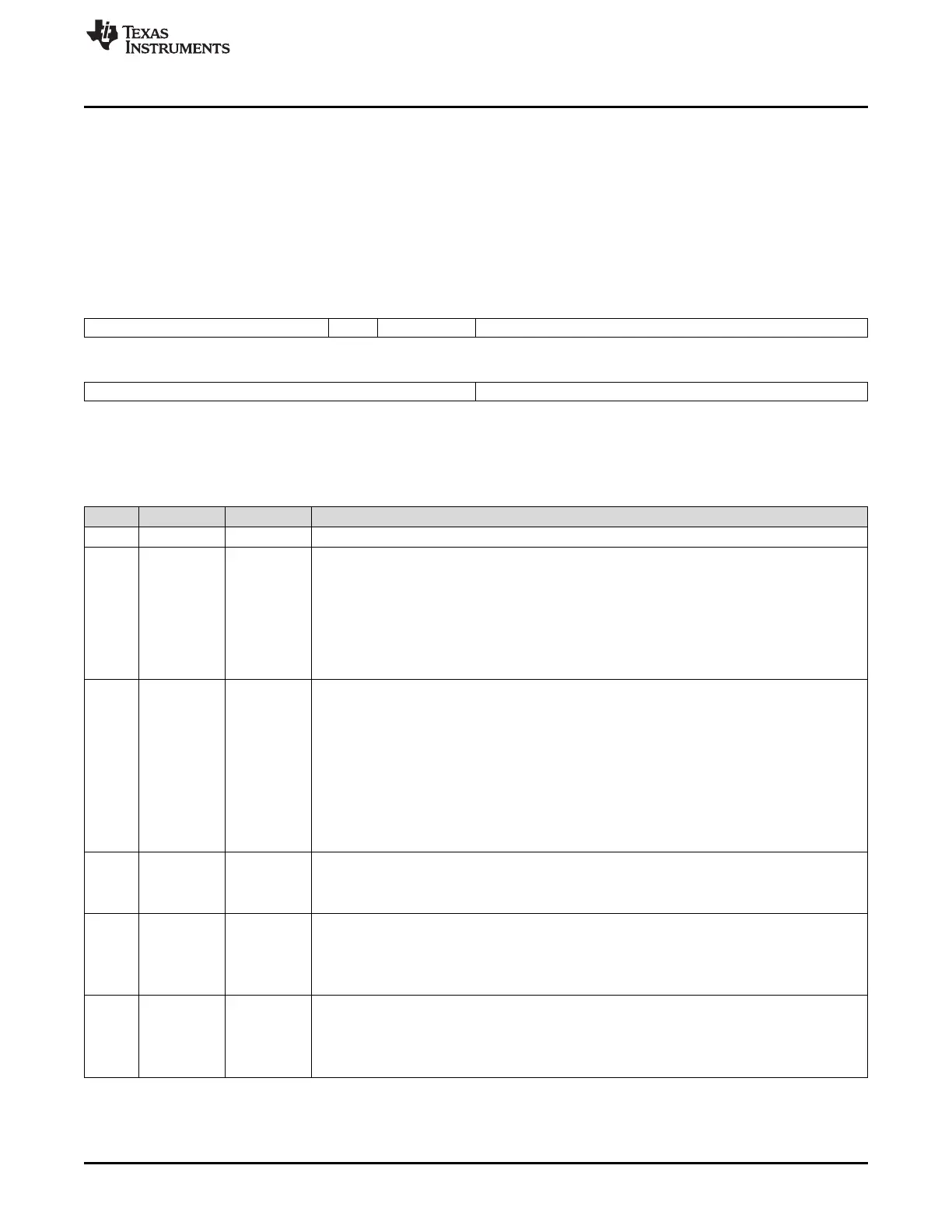
Figure 26-158. Message RAM Configuration Register (MRC) [offset_CC = 300h]
31 27 26 25 24 23 16
Reserved SPLM* SEC* LCB*
R-0 R-1h R-0 R/W-80h
15 8 7 0
FFB* FDB*
R/W-0 R/W-0
LEGEND: R/W = Read/Write; R = Read only; -n = value after reset; *These bits can be updated in DEFAULT_CONFIG or CONFIG state
only
Table 26-137. Message RAM Configuration Register (MRC) Field Descriptions
Bit Field Value Description
31-27 Reserved 0 Reads return 0. Writes have no effect.
26 SPLM Sync Frame Payload Multiplex. This bit is only evaluated if the node is configured as sync node
(SUCC1.TXSY = 1) or for single slot mode operation (SUCC1.TSM = 1). When this bit is set to 1
message buffers 0 and 1 are dedicated for sync frame transmission with different payload data on
channel A and B. When this bit is set to 0, sync frames are transmitted from message buffer 0 with
the same payload data on both channels. Note that the channel filter configuration for message
buffer 0 resp. message buffer 1 has to be chosen accordingly.
0 Only message buffer 0 is locked against reconfiguration.
1 Both message buffers 0 and 1 are locked against reconfiguration.
25-24 SEC Secure Buffers. Not evaluated when the communication controller is in DEFAULT_CONFIG or
CONFIG state.
0 Reconfiguration of message buffers is enabled with numbers < FFBh enabled.
Exception: In nodes configured for sync frame transmission or for single slot mode operation
message buffer 0 (and if SPLM = 1, also message buffer 1) is always locked.
1h Reconfiguration of message buffers with numbers < FDB and with numbers FFB is locked and
transmission of message buffers for static segment with numbers FDB is disabled.
2h Reconfiguration of all message buffers is locked.
3h Reconfiguration of all message buffers is locked and transmission of message buffers for static
segment with numbers FDB is disabled.
23-16 LCB Last configured buffer.
0-7Fh Number of message buffers is LCB + 1.
≥ 80h No message buffer is configured.
15-8 FFB First buffer of FIFO.
0 All message buffers are assigned to the FIFO.
0-7Fh Message buffers from FFB to LCB are assigned to the FIFO.
≥ 80h No message buffer is assigned to the FIFO.
7-0 FDB First dynamic buffer.
0 No group of pure static buffers is configured.
0-7Fh Message buffers 0 to FDB - 1 are reserved for static segment.
≥ 80h No dynamic buffers are configured.

 Loading...


