FlexRay Module Registers
www.ti.com
1388
SPNU563A–March 2018
Submit Documentation Feedback
Copyright © 2018, Texas Instruments Incorporated
FlexRay Module
NOTE: In case the node is configured as sync node (SUCC1.TXSY = 1) or for single slot mode
operation (SUCC1.TSM = 1), message buffer 0 resp. 1 is reserved for sync frames or single
slot frames and have to be configured with the node-specific key slot ID. In case the node is
neither configured as sync node nor for single slot operation message buffer 0 resp. 1 is
treated like all other message buffers.
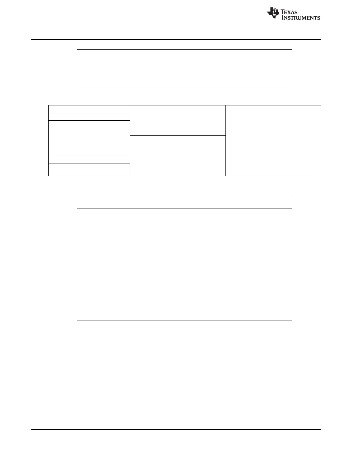
Table 26-138. Buffer Configuration
Message Buffer 0 ↓ Static Buffers
Message Buffer 1
. . . ↓ Static + Dynamic Buffers ← FDB
↓ FIFO ← FFB FIFO configured: FBB > FDB
No FIFO configured: FFB
≥ 128
Message Buffer N-1
Message Buffer N ← LCB LCB ≥ FDB,
LCB ≥ FFB
The programmer must ensure that the configuration defined by FDB(7-0), FFB(7-0), and LCB(7-0) is valid.
NOTE: The communication controller does not check for erroneous configurations.
NOTE: Maximum Number of Header Sections
The maximum number of header sections is 128. This means a maximum of 128 message
buffers can be configured. The maximum length of the data sections is 254 bytes. The length
of the data section may be configured different for each message buffer. In case two or more
message buffers are assigned to slot 1 by use of cycle filtering, all of them must be located
either in the "Static Buffers" or at the beginning of the "Static + Dynamic Buffers" section.
The FlexRay protocol specification requires that each node has to send a frame in its key
slot. Therefore at least message buffer 0 is reserved for transmission in the key slot. Due to
this requirement a maximum number of 127 message buffers can be assigned to the FIFO.
Nevertheless, a non protocol conform configuration without a transmission slot in the static
segment would still be operational. The payload length configured and the length of the data
sections need to be configured identical for all message buffers belonging to the FIFO via
WRHS2. PLC and WRHS3.DP. When the communication controller is not in
DEFAULT_CONFIG or CONFIG state reconfiguration of message buffers belonging to the
FIFO is locked.

 Loading...


