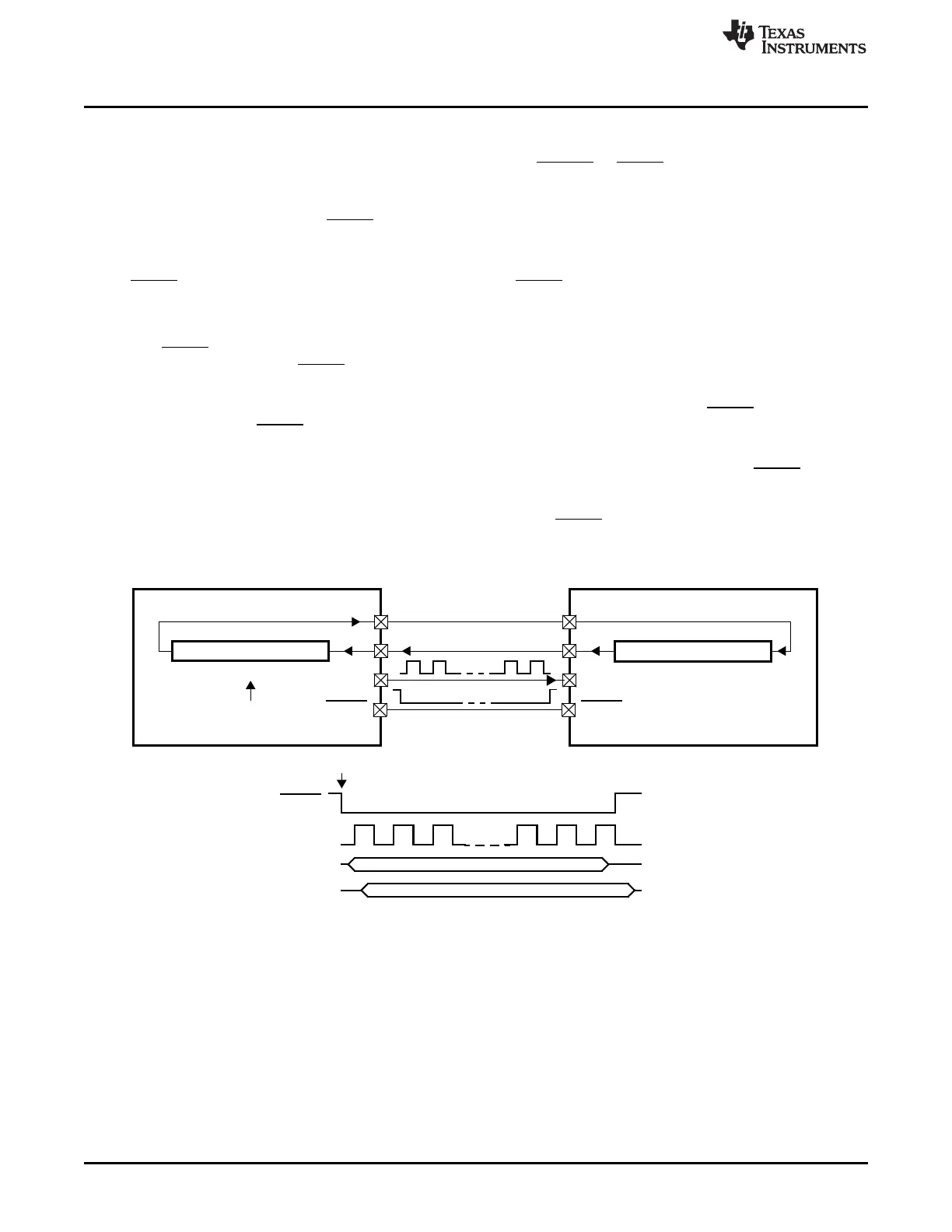
Master
Slave
(Master = 1; CLKMOD = 1) (Master = 0; CLKMOD = 0)
SPIDAT1 SPIDAT0
MSB LSB
MSB LSB
Write to SPIDAT1
SPISOMI SPISOMI
SPISIMO
SPICLK SPICLK
SPICS SPICS
Write to SPIDAT1
SPICLK
SPISIMO
SPISOMI
SPICS
SPISIMO
Basic Operation
www.ti.com
1508
SPNU563A–March 2018
Submit Documentation Feedback
Copyright © 2018, Texas Instruments Incorporated
Multi-Buffered Serial Peripheral Interface Module (MibSPI) with Parallel Pin
Option (MibSPIP)
28.2.5.2 Four-Pin Mode with Chip Select
The three-pin option and the four-pin option of the SPI / MibSPI are identical in the master mode
(CLKMOD = 1), except that the four-pin option uses either SPIENA or SPICS pins. The I/O directions of
these pins are determined by the CLKMOD control bit as SPI / MibSPI and is not general-purpose I/O.
28.2.5.2.1 Four-Pin Option with SPICS
In master mode, each chip select signal is used to select a specific slave. In slave mode, the chip select
signal is used to enable and disable the transfer. Chip-select functionality is enabled by setting one of the
SPICS pins as a chip select. It is disabled by setting all SPICS pins as GIOs in SPIPC0.
28.2.5.2.1.1 Multiple Chip Selects
The SPICS pins that are used must be configured as functional pins in the SPIPC0 register. The default
pattern to be put on the SPICS when all the slaves are deactivated is set in the SPIDEF register. This
pattern allows different slaves with different chip-select polarity to be activated by the SP/MibSPI.
The master-mode SPI is capable of driving either 0 or 1 as the active value for any SPICS output pin. The
drive state for the SPICS pins is controlled by the CSNR field of SPIDAT1. The pattern that is driven will
select the slave to which the transmission is dedicated.
In slave mode, the SPI can only be selected by an active value of 0 on any of its selected SPICS input
pins.
Figure 28-7. Operation with SPICS

 Loading...


