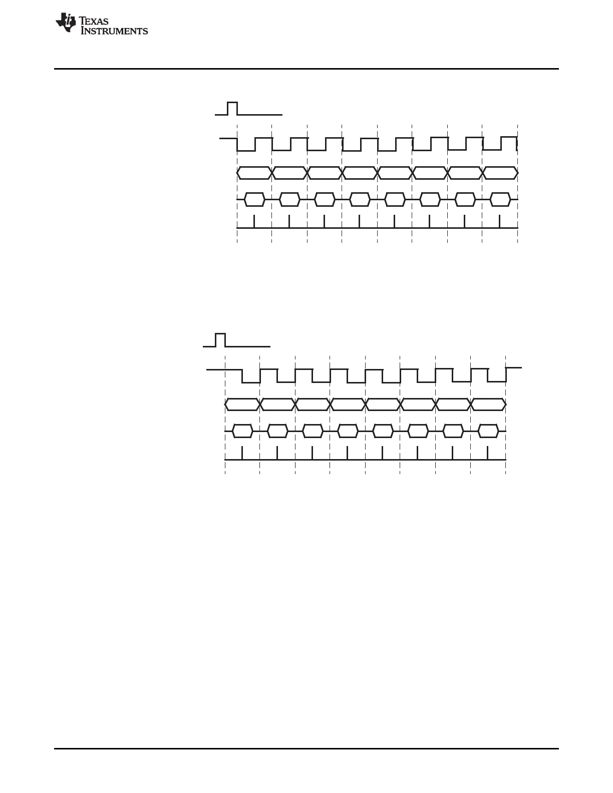
Data is output one-half cycle before the first falling edge of SPICLK and on the subsequent rising edges of SPICLK.
Input data is latched on the falling edge of SPICLK.
Write SPIDAT
SPICLK
SPISIMO
SPISOMI
receive sample
MSB
D6 D5 D4 D3 D2 D1
D0
LSB
D6 D5 D4 D3 D2 D1
D7
1
2
3 4 5 6 7 8
Data is output on the falling edge of SPICLK.
Input data is latched on the rising edge of SPICLK.
Write SPIDAT
SPISIMO
SPISOMI
receive sample
MSB
D6
D5 D4 D3 D2 D1
D0
LSB
D6 D5 D4 D3
D2
D1D7
1
2
3 4 5 6 7 8
SPICLK
www.ti.com
Basic Operation
1513
SPNU563A–March 2018
Submit Documentation Feedback
Copyright © 2018, Texas Instruments Incorporated
Multi-Buffered Serial Peripheral Interface Module (MibSPI) with Parallel Pin
Option (MibSPIP)
Figure 28-14. Clock Mode with Polarity = 1 and Phase = 0
Figure 28-15. Clock Mode with Polarity = 1 and Phase = 1

 Loading...


