www.ti.com
Control Registers
1565
SPNU563A–March 2018
Submit Documentation Feedback
Copyright © 2018, Texas Instruments Incorporated
Multi-Buffered Serial Peripheral Interface Module (MibSPI) with Parallel Pin
Option (MibSPIP)
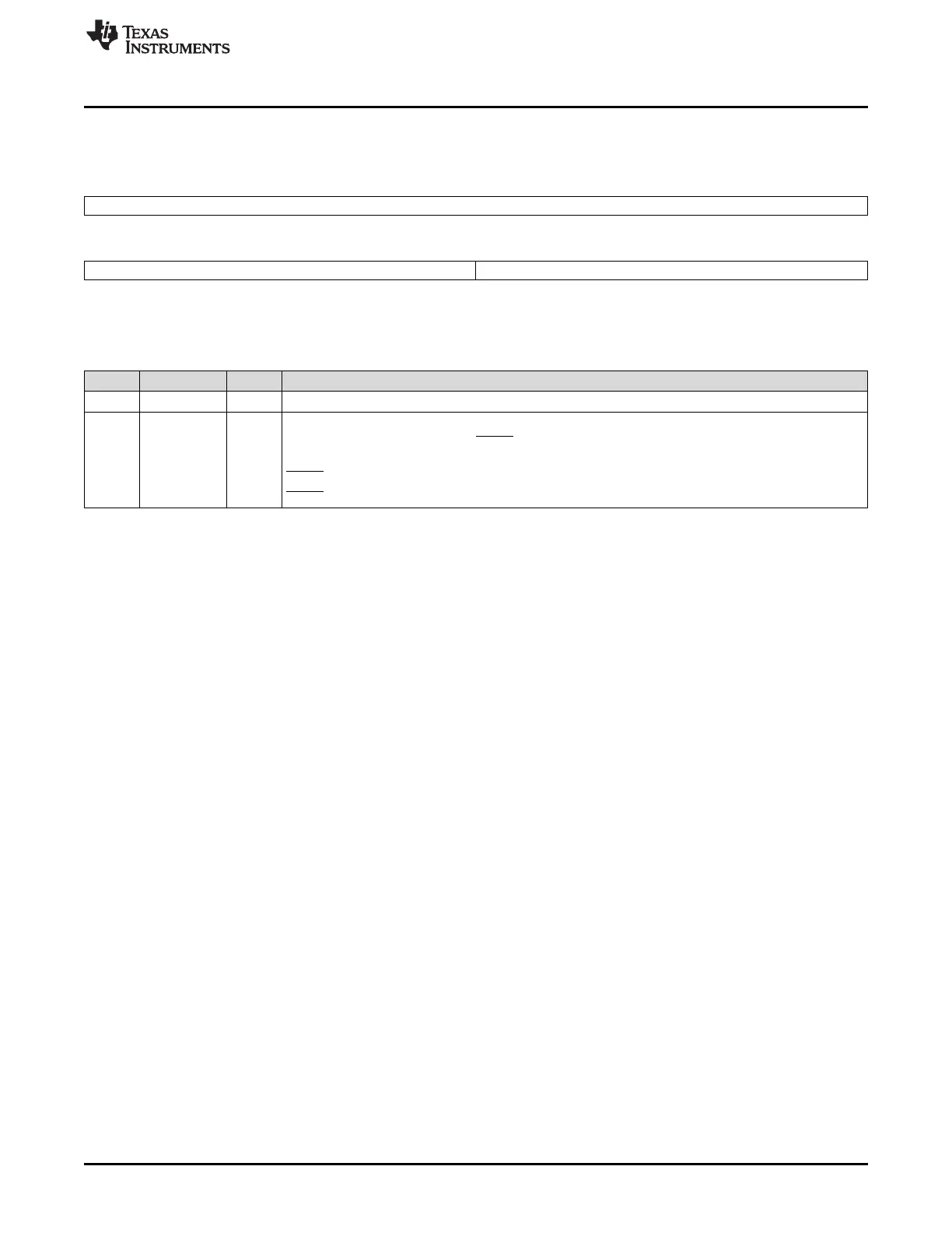
28.3.20 SPI Default Chip Select Register (SPIDEF)
Figure 28-55. SPI Default Chip Select Register (SPIDEF) [offset = 4Ch]
31 16
Reserved
R-0
15 8 7 0
Reserved CSDEF
R-0 R/W-FFh
LEGEND: R/W = Read/Write; R = Read only; -n = value after reset
Table 28-29. SPI Default Chip Select Register (SPIDEF) Field Descriptions
Bit Field Value Description
31-8 Reserved 0 Reads return 0. Writes have no effect.
7-0 CDEF Chip select default pattern. Master-mode only.
The CSDEF bits are output to the SPICS pins when no transmission is being performed. It allows the
user to set a programmable chip-select pattern that deselects all of the SPI slaves.
0 SPICS is cleared to 0 when no transfer is active.
1 SPICS is set to 1 when no transfer is active.

 Loading...


