Multi-buffer RAM
www.ti.com
1608
SPNU563A–March 2018
Submit Documentation Feedback
Copyright © 2018, Texas Instruments Incorporated
Multi-Buffered Serial Peripheral Interface Module (MibSPI) with Parallel Pin
Option (MibSPIP)
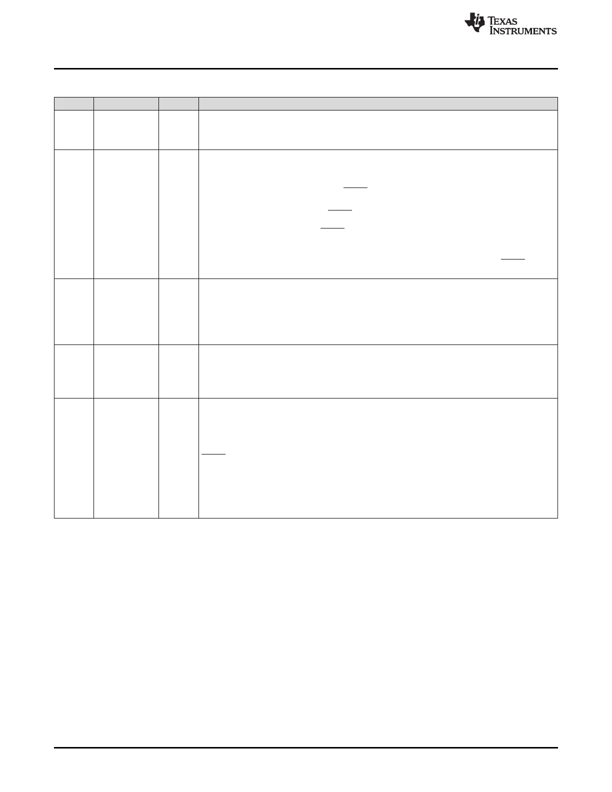
Table 28-62. Multi-buffer RAM Transmit Data Register (TXRAM) Field Descriptions (continued)
Bit Field Value Description
27 LOCK Lock two consecutive buffer words. Do not allow interruption by TG's with higher priority.
0 Any higher-priority TG can begin at the end of the current transaction.
1 A higher-priority TG cannot occur until after the next unlocked buffer word is transferred.
26 WDEL Enable the delay counter at the end of the current transaction.
Note: The WDEL bit is supported in master mode only. In slave mode, this bit will be
ignored.
0 No delay will be inserted. However, the SPICS pins will still be de-activated for at least for 2VCLK
cycles if CSHOLD = 0.
Note: The duration for which the SPICS pin remains deactivated also depends upon the time
taken to supply a new word after completing the shift operation (in compatibility mode). If
TXBUF is already full, then the SPICS pin will be deasserted for at least two VCLK cycles (if
WDEL = 0).
1 After a transaction, WDELAY of the corresponding data format will be loaded into the delay
counter. No transaction will be performed until the WDELAY counter overflows. The SPICS pins
will be de-activated for at least (WDELAY + 2) × VCLK_Period duration.
25-24 DFSEL Data word format select.
0 Data word format 0 is selected.
1h Data word format 1 is selected.
2h Data word format 2 is selected.
3h Data word format 3 is selected.
23-16 CSNR 0-FFh Chip select (CS) number. CSNR defines the chip select pins that will be activated during the data
transfer. CSNR is a bit-mask that controls all chip select pins. See Table 28-63.
Note: If your MibSPI has less than 8 chip select pins, all unused upper bits will be 0. For
example, MiBSPI3 has 6 chip select pins, if you write FFh to CSNR, the actual number
stored in CSNR is 3Fh.
15-0 TXDATA 0-7FFFh Transfer data. When written, these bits are copied to the shift register if it is empty. If the shift
register is not empty, then they are held in TXBUF.
SPIEN must be set to 1 before this register can be written to. Writing a 0 to SPIEN forces the lower
16 bits of TXDATA to 0.
A write to this register (or to the TXDATA field only) drives the contents of the CSNR field on the
SPICS pins, if the pins are configured as functional pins (automatic chip select, see
Section 28.2.1).
When this register is read, the contents of TXBUF, which holds the latest data written, will be
returned.
Note: Regardless of the character length, the transmit data should be right-justified before
writing to the SPIDAT1 register.

 Loading...


