.
.
.
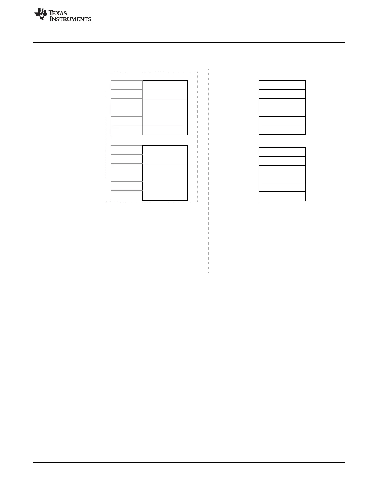
TXBUF0
TXBUF1
TXBUF126
TXBUF127
Parity/ECC0
Parity/ECC1
0
31
Address
BASE+0x000h
BASE+0x1FFh
BASE+0x200h
BASE+0x3FFh
.
.
.
.
.
.
TXParity/ECC0
TXParity/ECC1
TXParity/ECC126
TXParity/ECC127
RXParity/ECC0
RXParity/ECC1
RXParity/ECC126
RXParity/ECC127
0
31
Multibuffer RAM
Address
BASE+0x400h
BASE+0x5FFh
BASE+0x600h
BASE+0x7FFh
Memory organization during Normal Operation
BASE - Base Address of Multibuffer RAM
Refer to specific Device Datasheet
for the actual value of BASE.
*
.
.
Parity/ECC127
Parity/ECC126
.
.
.
RXBUF0
RXBUF1
RXBUF126
RXBUF127
0
31
(Parity/ECC locations are not accessible by CPU)
Parity/ECC0
Parity/ECC1
.
.
Parity/ECC127
Parity/ECC126
Parity/ECC memory organization during Test Mode
www.ti.com
Parity\ECC Memory
1613
SPNU563A–March 2018
Submit Documentation Feedback
Copyright © 2018, Texas Instruments Incorporated
Multi-Buffered Serial Peripheral Interface Module (MibSPI) with Parallel Pin
Option (MibSPIP)
Figure 28-90. Memory-Map for Parity Locations During Normal and Test Mode While EXTENDED_BUF
Mode is Disabled or the Feature is Not Implemented

 Loading...


