SPICS
* ENABLE_HIGHZ is set to 1 in Slave SPI
VCLK
SPIENA
SPICLK
* Diagram shows relationship between the
SPICS
from a Master to
SPIENA
from Slave SPI when
SPIENA
is configured in High-Impedance mode
Write to SPIDAT
SPICS
* ENABLE_HIGHZ is cleared to 0 in Slave SPI
VCLK
SPIENA
SPICLK
* Diagram shows relationship between the
SPICS
from a Master to
SPIENA
from Slave SPI when
SPIENA
is configured in Push-Pull mode
Write to SPIDAT
VCLK
SPIENA
* Diagram shows a relationship between the SPIENA from Slave and SPICLK from Master
Write to SPIDAT
SPICLK
VCLK
SPICLK
SPISOMI
SPISIMO
* Dotted vertical lines indicate the receive edges
Write to SPIDAT
www.ti.com
MibSPI Pin Timing Parameters
1619
SPNU563A–March 2018
Submit Documentation Feedback
Copyright © 2018, Texas Instruments Incorporated
Multi-Buffered Serial Peripheral Interface Module (MibSPI) with Parallel Pin
Option (MibSPIP)
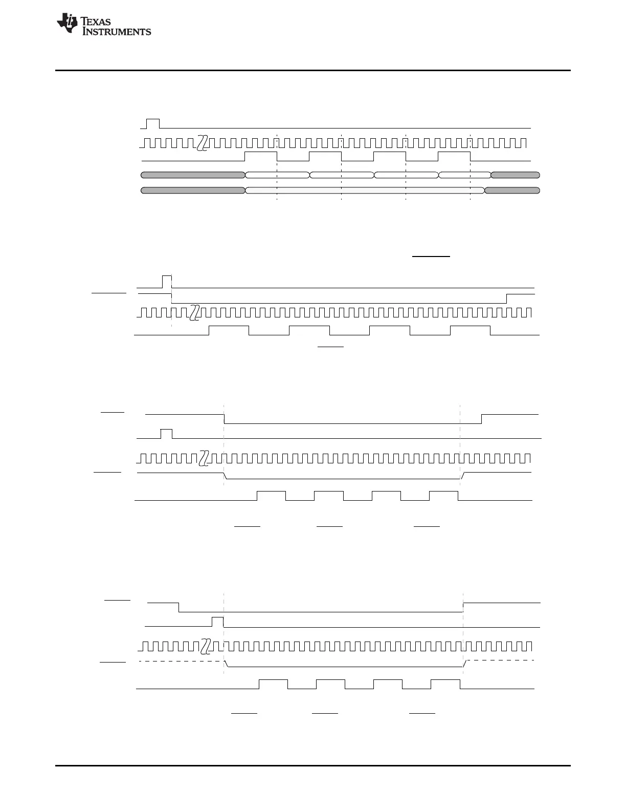
28.6.2 Slave Mode Timings for SPI/MibSPI
Figure 28-98. SPI/MibSPI Pins During Slave Mode 3-Pin Configuration
Figure 28-99. SPI/MibSPI Pins During Slave Mode in 4-Pin with SPIENA Configuration
Figure 28-100. SPI/MibSPI Pins During Slave Mode in 5-Pin Configuration (Single Slave)
Figure 28-101. SPI/MibSPI Pins During Slave Mode in 5-Pin Configuration (Single/Multi-Slave)

 Loading...


