Start
0
(LSBit)
1 2 3 4 5 6
7
(MSBit)
Addr Parity
Start
0
(LSBit)
1 2 3 4 5 6
7
(MSBit)
Parity
Idle-line mode
Address bit mode
Address bit
Stop
Stop
www.ti.com
SCI
1627
SPNU563A–March 2018
Submit Documentation Feedback
Copyright © 2018, Texas Instruments Incorporated
Serial Communication Interface (SCI)/ Local Interconnect Network (LIN)
Module
29.2 SCI
29.2.1 SCI Communication Formats
The SCI module can be configured to meet the requirements of many applications. Because
communication formats vary depending on the specific application, many attributes of the SCI/LIN are user
configurable. The list below describes these configuration options:
• SCI Frame format
• SCI Timing modes
• SCI Baud rate
• SCI Multiprocessor modes
29.2.1.1 SCI Frame Formats
The SCI uses a programmable frame format. All frames consist of the following:
• One start bit
• One to eight data bits
• Zero or one address bit
• Zero or one parity bit
• One or two stop bits
The frame format for both the transmitter and receiver is programmable through the bits in the SCIGCR1
register. Both receive and transmit data is in nonreturn to zero (NRZ) format, which means that the
transmit and receive lines are at logic high when idle. Each frame transmission begins with a start bit, in
which the transmitter pulls the SCI line low (logic low). Following the start bit, the frame data is sent and
received least significant bit first (LSB).
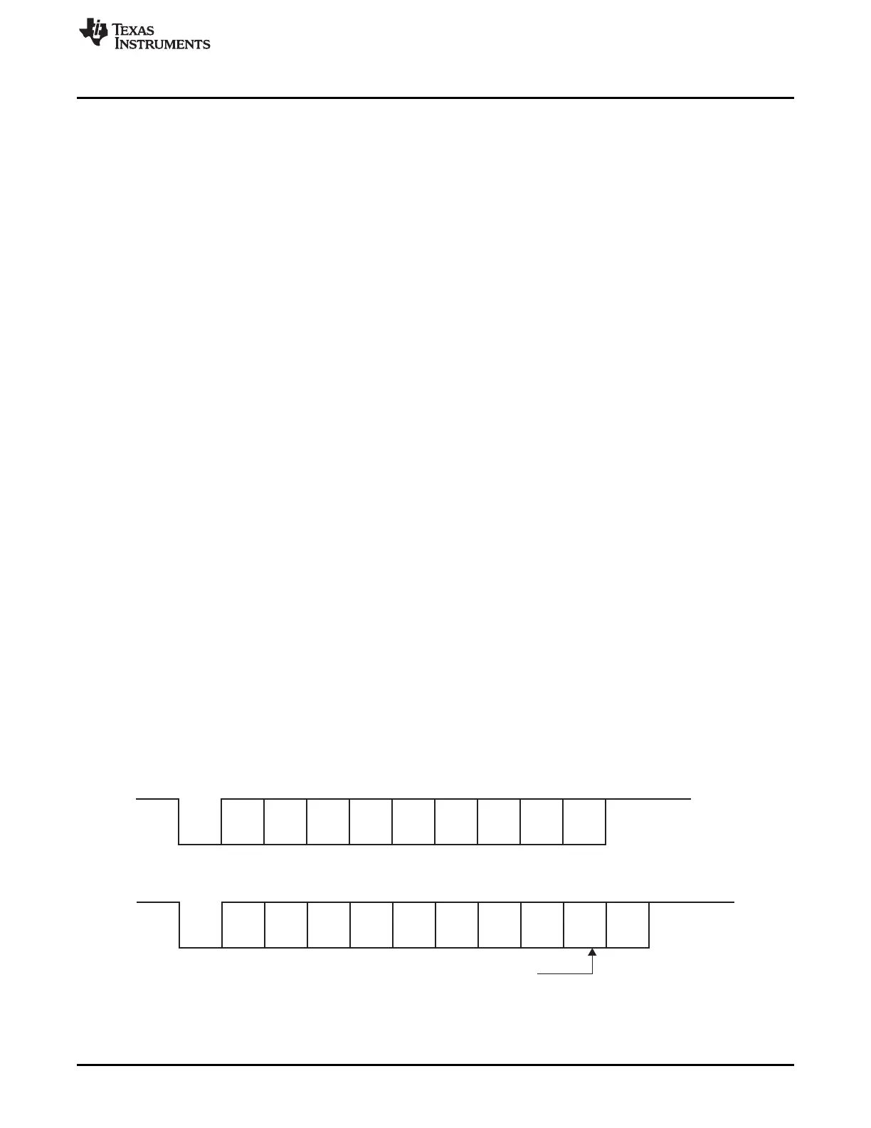
An address bit is present in each frame if the SCI is configured to be in address-bit mode but is not
present in any frame if the SCI is configured for idle-line mode. The format of frames with and without the
address bit is illustrated in Figure 29-3.
A parity bit is present in every frame when the PARITY ENA bit is set. The value of the parity bit depends
on the number of one bits in the frame and whether odd or even parity has been selected via the PARITY
ENA bit. Both examples in Figure 29-3 have parity enabled.
All frames include one stop bit, which is always a high level. This high level at the end of each frame is
used to indicate the end of a frame to ensure synchronization between communicating devices. Two stop
bits are transmitted if the STOP bit in SCIGCR1 register is set. The examples shown in Figure 29-3 use
one stop bit per frame.
Figure 29-3. Typical SCI Data Frame Formats

 Loading...


