V C L K
a
Td
M
Pb itT
ú
û
ù
ê
ë
é
+
÷
ø
ö
ç
è
æ
++=
1 6
11 6
VCLK
i
Td
M
PbitT
ú
û
ù
ê
ë
é
+
÷
ø
ö
ç
è
æ
++=
16
116
SCICLK Frequency =
Asynchronous baud value =
For P = 0,
Asynchronous baud value =
VCLK Frequency
P 1
M
16
------+ +
----------------------------------------------------
SCICLK Frequency
16
----------------------------------------------------------
VCLK Frequency
32
-------------------------------------------------
www.ti.com
SCI
1629
SPNU563A–March 2018
Submit Documentation Feedback
Copyright © 2018, Texas Instruments Incorporated
Serial Communication Interface (SCI)/ Local Interconnect Network (LIN)
Module
In asynchronous timing mode, the SCI generates a baud clock according to the following formula:
(42)
29.2.1.3.1 Superfractional Divider, SCI Asynchronous Mode
The superfractional divider is available in SCI asynchronous mode (idle-line and address-bit mode).
Building on the 4-bit fractional divider M (BRS[27:24]), the superfractional divider uses an additional 3-bit
modulating value (see Table 29-2). The bits with a 1 in the table will have an additional VCLK period
added to their T
bit
. If the character length is more than 10, then the modulation table will be a rolled-over
version of the original table (Table 29-1), as shown in Table 29-2.
The baud rate will vary over a data field to average according to the BRS[30:28] value by a “d” fraction of
the peripheral internal clock: 0<d<1. See Figure 29-5 for a simple Average “d’ calculation based on “U”
value (BRS[30:28]).
The instantaneous bit time is expressed in terms of T
VCLK
as follows:
For all P other than 0, and all M and d (0 or 1),
(43)
For P = 0 T
bit
= 32T
VCLK
The averaged bit time is expressed in terms of T
VCLK
as follows:
For all P other than 0, and all M and d (0<d<1),
(44)
For P = 0 T
bit
= 32T
VCLK
(1)
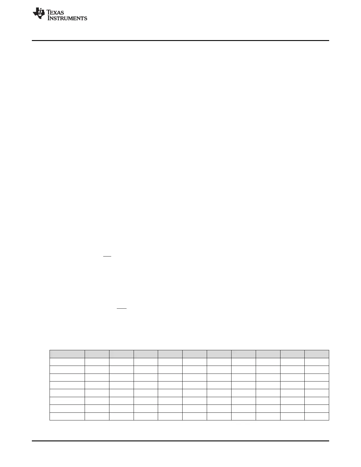
Normal configuration = Start + 8 Data Bits + Stop Bit
Table 29-1. Superfractional Bit Modulation for SCI Mode (Normal Configuration)
(1)
BRS[30:28] Start Bit D[0] D[1] D[2] D[3] D[4] D[5] D[6] D[7] Stop Bit
0h 0 0 0 0 0 0 0 0 0 0
1h 1 0 0 0 0 0 0 0 1 0
2h 1 0 0 0 1 0 0 0 1 0
3h 1 0 1 0 1 0 0 0 1 0
4h 1 0 1 0 1 0 1 0 1 0
5h 1 1 1 0 1 0 1 0 1 1
6h 1 1 1 0 1 1 1 0 1 1
7h 1 1 1 1 1 1 1 0 1 1

 Loading...


