WAKEUP SIGNAL
BUS IN SLEEP MODE
T
WUSIG
SYNCH BREAK
T
INITIALIZE
BUS IN
OPERATIONAL MODE
www.ti.com
Low-Power Mode
1663
SPNU563A–March 2018
Submit Documentation Feedback
Copyright © 2018, Texas Instruments Incorporated
Serial Communication Interface (SCI)/ Local Interconnect Network (LIN)
Module
29.4.2 Wakeup
The wakeup interrupt is used to allow the SCI/LIN module to automatically exit low-power mode. A
SCI/LIN wakeup is triggered when a low level is detected on the receive RX pin, and this clears the
POWERDOWN bit.
NOTE: If the wakeup interrupt is disabled then the SCI/LIN enters low-power mode whenever it is
requested to do so, but a low level on the receive RX pin does NOT cause the SCI/LIN to
exit low-power mode.
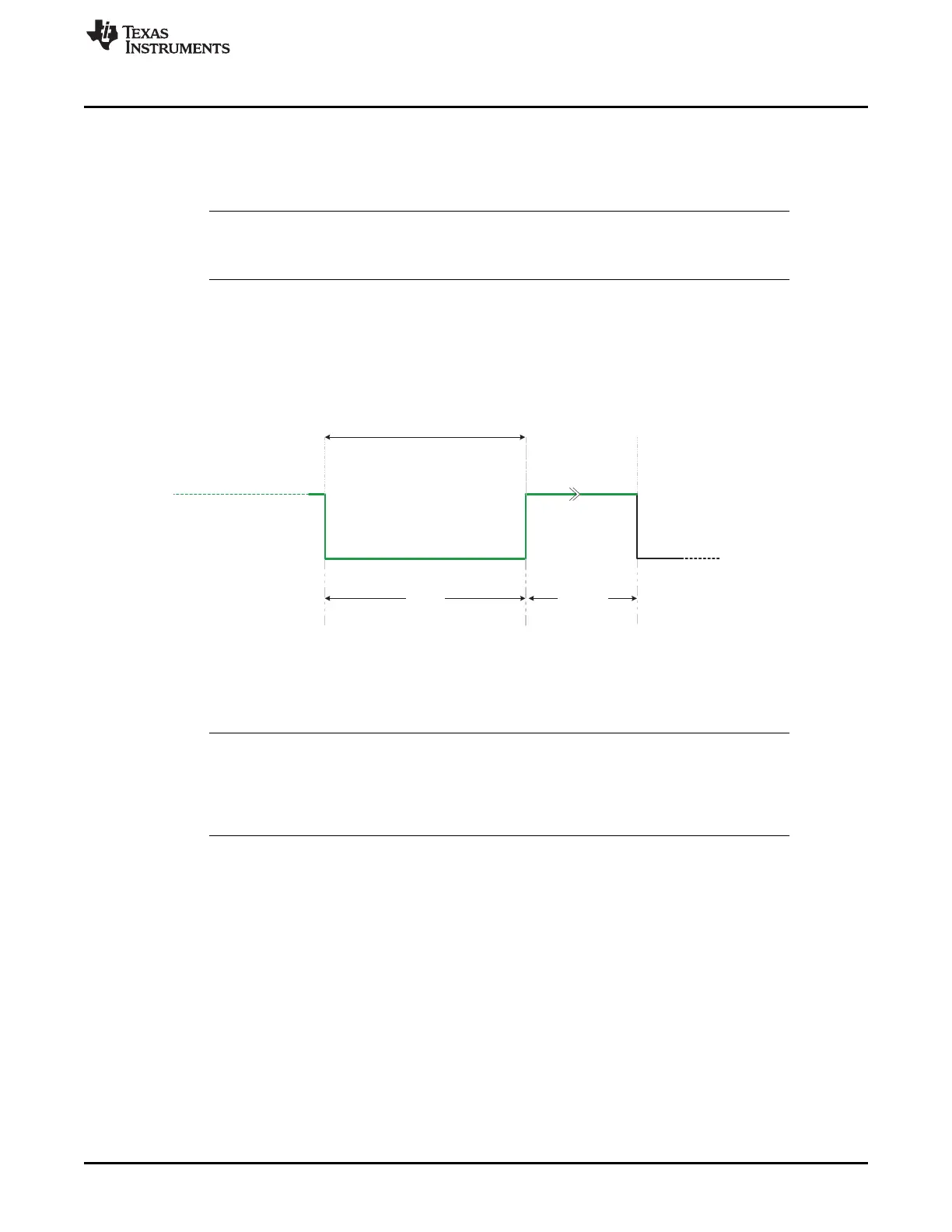
In LIN mode, any node can terminate sleep mode by sending a wakeup signal; see Figure 29-26. A slave
node that detects the bus in sleep mode, and with a wakeup request pending, will send a wakeup signal.
The wakeup signal is a dominant value on the LIN bus for T
WUSIG
; this is at least 5 T
bits
for the LIN bus
baud rates. The wakeup signal is generated by sending an 0xF0 byte containing 5 dominant T
bits
and 5
recessive T
bits
.
Figure 29-26. Wakeup Signal Generation
(51)
Assuming a perfect bus with no noise or loading effects, a write of 0xF0 to TD0 will load the transmitter to
meet the wakeup signal timing requirement for T
WUSIG
. Then, setting the GENWU bit will transmit the
preloaded value in TD0 for a wakeup signal transmission.
NOTE: The GENWU bit can be set/reset only when SWnRST is set to’1’ and the node is in power
down mode. The bit will be cleared on a valid synch break detection. A master sending a
wakeup request, will exit power down mode upon reception of the wakeup pulse. The bit will
be cleared on a SWnRST. This can be used to stop a master from sending further wakeup
requests.
The TI TPIC1021 LIN transceiver, upon receiving a wakeup signal, will translate it to the microcontroller
for wakeup with a dominant level on the RX pin, or a signal to the voltage regulator. While the
POWERDOWN bit is set, if the LIN module detects a recessive-to-dominant edge (falling edge) on the RX
pin, it will generate a wakeup interrupt if enabled in the SCISETINT register.
According to LIN protocol 2.0, the TI TPIC1021 LIN transceiver detecting a dominant level on the bus
longer than 150 ms will detect it as a wakeup request. The LIN controller’s slave is ready to listen to the
bus in less than 100 ms (T
INITIALIZE
<100ms) after a dominant-to-recessive edge (end-of-wakeup signal).

 Loading...


