www.ti.com
SCI/LIN Control Registers
1685
SPNU563A–March 2018
Submit Documentation Feedback
Copyright © 2018, Texas Instruments Incorporated
Serial Communication Interface (SCI)/ Local Interconnect Network (LIN)
Module
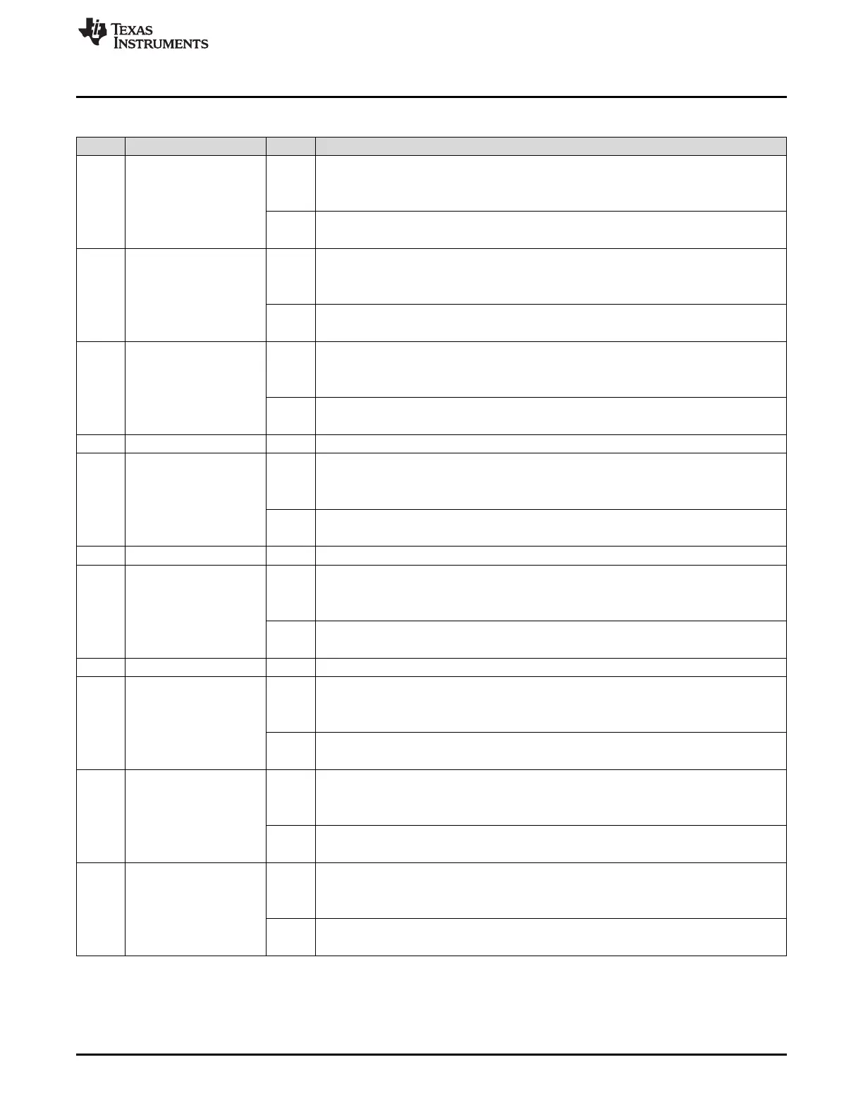
Table 29-19. SCI Clear Interrupt Level Register (SCICLEARINTLVL) Field Descriptions (continued)
Bit Field Value Description
26 CLR FE INT LVL Clear framing-error interrupt. This bit is effective in LIN or SCI-compatible mode.
0 Read: The interrupt level is mapped to the INT0 line.
Write: No effect.
1 Read: The interrupt level is mapped to the INT1 line.
Write: The interrupt level is mapped to the INT0 line.
25 CLR OE INT LVL Clear overrun-error interrupt. This bit is effective in LIN or SCI-compatible mode.
0 Read: The interrupt level is mapped to the INT0 line.
Write: No effect.
1 Read: The interrupt level is mapped to the INT1 line.
Write: The interrupt level is mapped to the INT0 line.
24 CLR PE INT LVL Clear parity interrupt. This bit is effective in LIN or SCI-compatible mode.
0 Read: The interrupt level is mapped to the INT0 line.
Write: No effect.
1 Read: The interrupt level is mapped to the INT1 line.
Write: The interrupt level is mapped to the INT0 line.
23-19 Reserved 0 Reads return 0. Writes have no effect.
18 CLR RX DMA ALL LVL Clear receive DMA interrupt level. This bit is effective in SCI-compatible mode only.
0 Read: The receive interrupt request for address frames is mapped to the INT0 line.
Write: No effect.
1 Read: The receive interrupt request for address frames is mapped to the INT1 line.
Write: The receive interrupt request for address frames is mapped to the INT0 line.
17-14 Reserved 0 Reads return 0. Writes have no effect.
13 CLR ID INT LVL Clear ID interrupt. This bit is effective in LIN mode only.
0 Read: The interrupt level is mapped to the INT0 line.
Write: No effect.
1 Read: The interrupt level is mapped to the INT1 line.
Write: The interrupt level is mapped to the INT0 line.
12-10 Reserved 0 Reads return 0. Writes have no effect.
9 CLR RX INT LVL Clear receiver interrupt. This bit is effective in LIN or SCI-compatible mode.
0 Read: The interrupt level is mapped to the INT0 line.
Write: No effect.
1 Read: The interrupt level is mapped to the INT1 line.
Write: The interrupt level is mapped to the INT0 line.
8 CLR TX INT LVL Clear transmitter interrupt. This bit is effective in LIN or SCI-compatible mode.
0 Read: The interrupt level is mapped to the INT0 line.
Write: No effect.
1 Read: The interrupt level is mapped to the INT1 line.
Write: The interrupt level is mapped to the INT0 line.
7 CLR TOA3WUS INT LVL Clear timeout after three wakeup signals interrupt. This bit is effective in LIN mode only.
0 Read: The interrupt level is mapped to the INT0 line.
Write: No effect.
1 Read: The interrupt level is mapped to the INT1 line.
Write: The interrupt level is mapped to the INT0 line.

 Loading...


