UP
DOWN
UP
DOWN
2
0
3
4
1
2
3
1
2
0
3
4
1
2
0
3
1
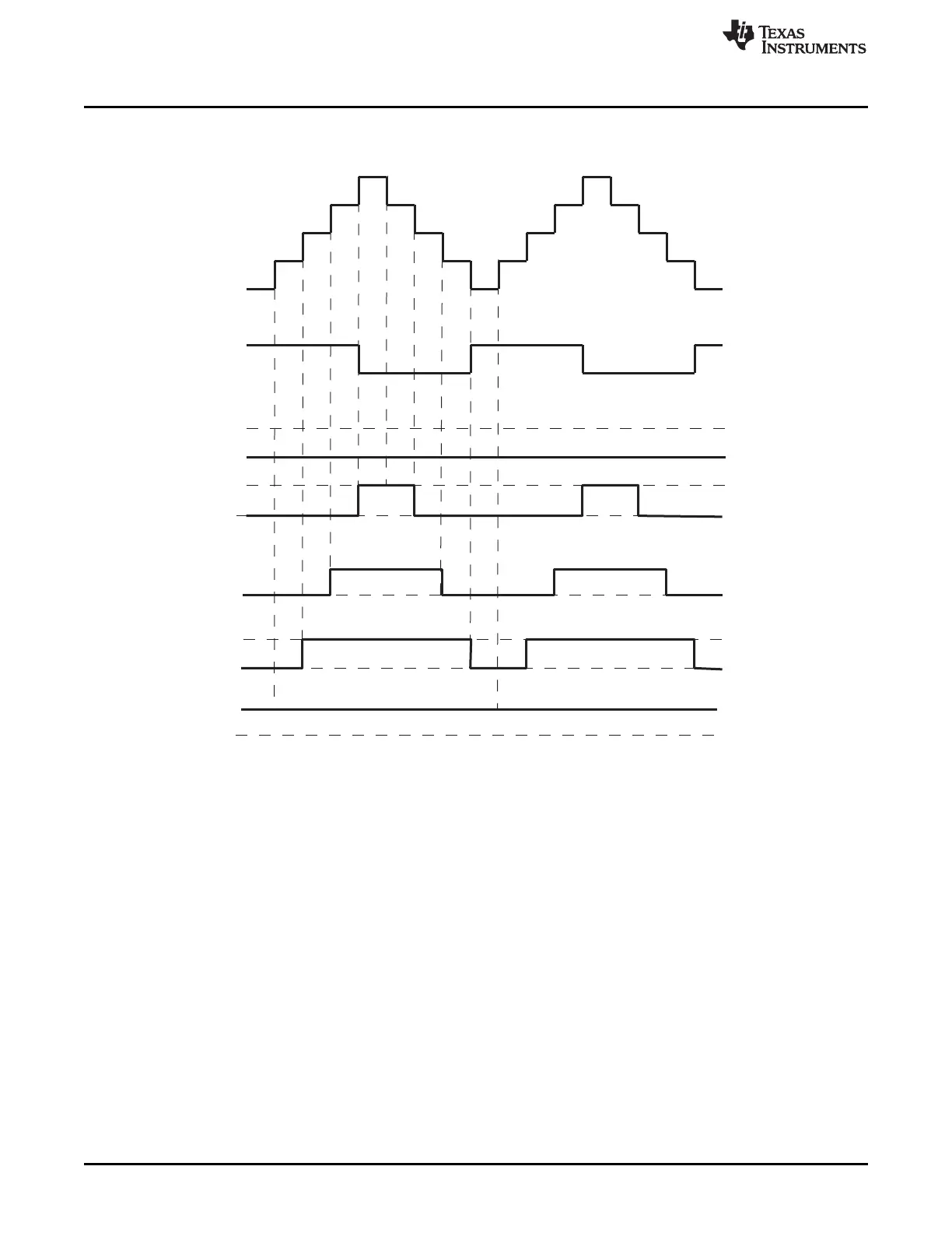
TBCTR
TBCTRDirection
EPWMxA/EPWMxB
Case2:
CMPA =3,25%Duty
Case3:
CMPA =2,50%Duty
Case3:
CMPA =1,75%Duty
Case4:
CMPA =0,100%Duty
Case1:
CMPA =4,0%Duty
EPWMxA/EPWMxB
EPWMxA/EPWMxB
EPWMxA/EPWMxB
EPWMxA/EPWMxB
Mode:Up-DownCount
TBPRD=4
CAU=SET,CAD=CLEAR
0%-100%Duty
ePWM Submodules
www.ti.com
2020
SPNU563A–March 2018
Submit Documentation Feedback
Copyright © 2018, Texas Instruments Incorporated
Enhanced Pulse Width Modulator (ePWM) Module
Figure 35-20. Up-Down-Count Mode Symmetrical Waveform
The PWM waveforms in Figure 35-21 through Figure 35-26 show some common action-qualifier
configurations. The C-code samples in Example 35-1 through Example 35-6 shows how to configure an
ePWM module for each case. Some conventions used in the figures and examples are as follows:
• TBPRD, CMPA, and CMPB refer to the value written in their respective registers. The active register,
not the shadow register, is used by the hardware.
• CMPx, refers to either CMPA or CMPB.
• EPWMxA and EPWMxB refer to the output signals from ePWMx
• Up-Down means Count-up-and-down mode, Up means up-count mode and Dwn means down-count
mode
• Sym = Symmetric, Asym = Asymmetric
Example 35-1 contains a code sample showing initialization and run time for the waveforms in Figure 35-
21.

 Loading...


