CTR=zero
CTR=CMPB
X
En
SyncOut
Phase reg
Ext SyncIn
(optional)
EPWM1A
EPWM1B
SyncOut
Phase reg
CTR=CMPB
CTR=zero
X
En
EPWM2B
EPWM2A
Master2
Master1
SyncIn
CTR=zero
CTR=CMPB
SyncOut
X
EPWM3B
Phase reg
Master3
En
EPWM3A
1
2
3
Φ=X
Φ=X
Φ=X
CTR=zero
CTR=CMPB
SyncOut
X
EPWM4B
Phase reg
Master4
En
EPWM4A
3
Φ=X
Buck #1
Vout1Vin1
EPWM1A
Buck #2
Vin2
EPWM2A
Vout2
Buck #4
Buck #3
Vin3
EPWM4A
Vin4
EPWM3A
Vout3
Vout4
SyncIn
SyncIn
SyncIn
www.ti.com
Application Examples
2057
SPNU563A–March 2018
Submit Documentation Feedback
Copyright © 2018, Texas Instruments Incorporated
Enhanced Pulse Width Modulator (ePWM) Module
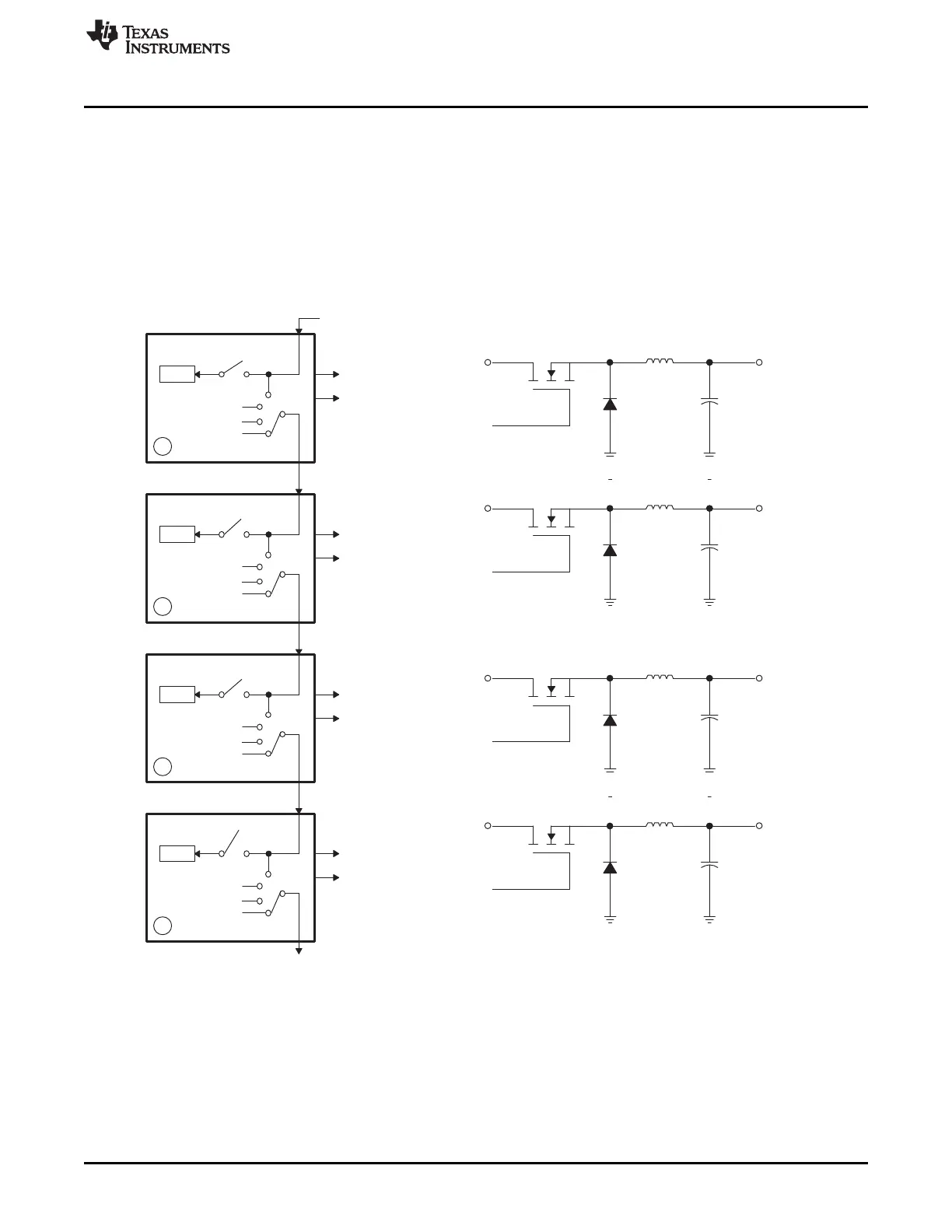
35.3.3 Controlling Multiple Buck Converters With Independent Frequencies
One of the simplest power converter topologies is the buck. A single ePWM module configured as a
master can control two buck stages with the same PWM frequency. If independent frequency control is
required for each buck converter, then one ePWM module must be allocated for each converter stage.
Figure 35-53 shows four buck stages, each running at independent frequencies. In this case, all four
ePWM modules are configured as Masters and no synchronization is used. Figure 35-54 shows the
waveforms generated by the setup shown in Figure 35-53; note that only three waveforms are shown,
although there are four stages.
Figure 35-53. Control of Four Buck Stages. Here F
PWM1
≠ F
PWM2
≠ F
PWM3
≠ F
PWM4
NOTE: Θ = X indicates value in phase register is a "don't care"

 Loading...


