EasyManuals Logo

Texas Instruments TMS570LC4357 User Manual

Texas Instruments TMS570LC4357
2208 pages
To Next Page IconTo Next Page
To Previous Page IconTo Previous Page
Page #2156 background imageLoading...
Page #2156 background image
Per1
Per2
PerN
Per1
Per2
PerN
PCR1 PCR3
Lower
256k
L2 SRAM
Upper
256k
L2 SRAM
CPU Interconnect Subsystem Peripheral Interconnect Subsystem
CPU
FIFO1
FIFO2
FIFO3
FIFO4
RAM Trace Port
SERIALIZER
RTPENA
RTPSYNC
RTPCLK
RTPDATA[x]
RTPDATA[0]
Overview
www.ti.com
2156
SPNU563AMarch 2018
Submit Documentation Feedback
Copyright © 2018, Texas Instruments Incorporated
RAM Trace Port (RTP)
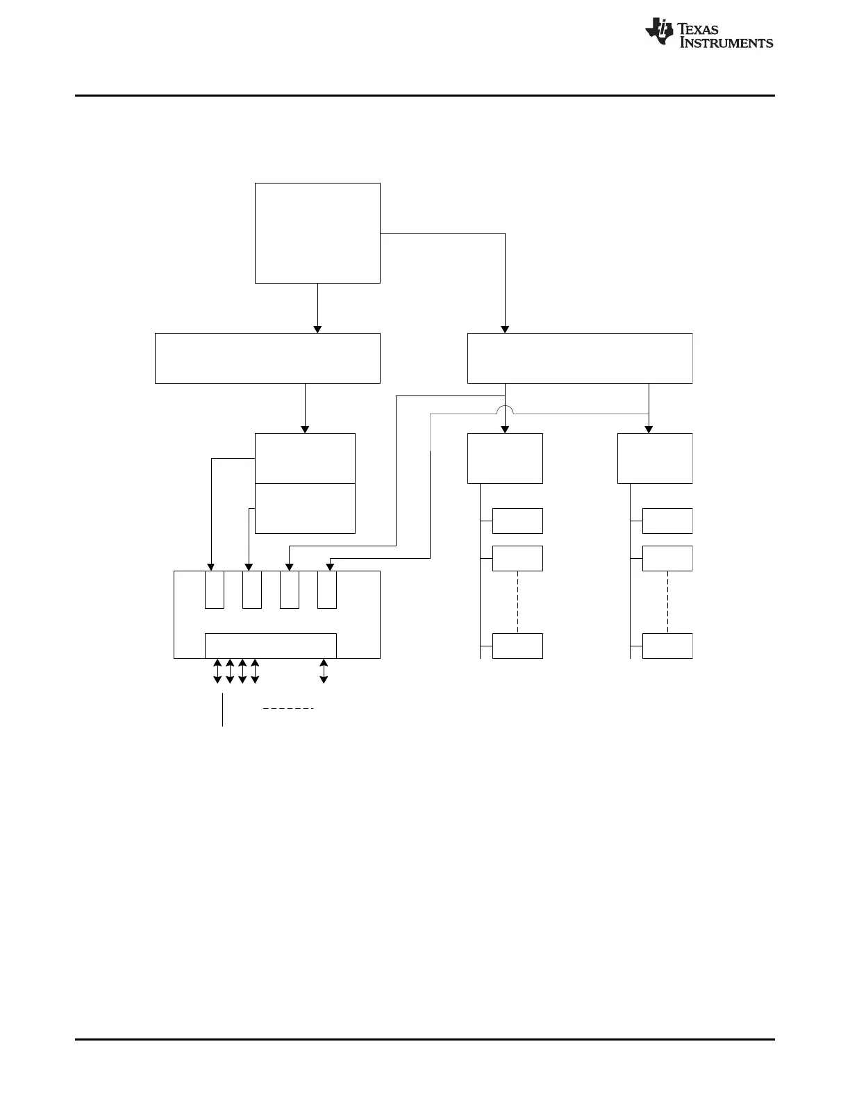
37.1.2 Block Diagram
Figure 37-1 is a block diagram of the RTP.
Figure 37-1. RAM Trace Port Module Block Diagram

Table of Contents

Questions and Answers:

Question and Answer IconNeed help?

Do you have a question about the Texas Instruments TMS570LC4357 and is the answer not in the manual?

Texas Instruments TMS570LC4357 Specifications

General IconGeneral
BrandTexas Instruments
ModelTMS570LC4357
CategoryMicrocontrollers
LanguageEnglish

Related product manuals