www.ti.com
RTP Control Registers
2171
SPNU563A–March 2018
Submit Documentation Feedback
Copyright © 2018, Texas Instruments Incorporated
RAM Trace Port (RTP)
37.3.4 RTP RAM 1 Trace Region Registers (RTPRAM1REG[1:2])
Figure 37-12 and Table 37-13 illustrate these registers.
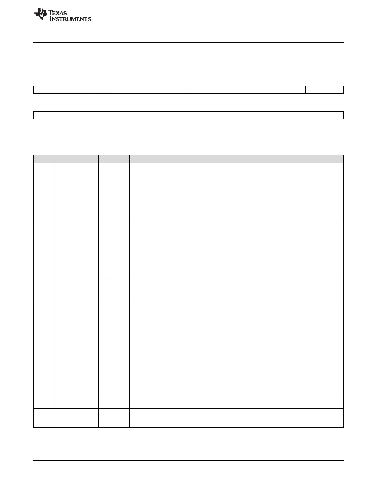
Figure 37-12. RTP RAM 1 Trace Region Registers (RTPRAM1REGn) (offset = 0Ch and 10h)
31 29 28 27 24 23 18 17 16
CPU_DMA RW BLOCKSIZE Reserved STARTADDR
R/WP-0 R/WP-0 R/WP-0 R-0 R/WP-0
15 0
STARTADDR
R/WP-0
LEGEND: R/W = Read/Write; R = Read only; WP = Write in privileged mode only; -n = value after reset
Table 37-13. RTP RAM 1 Trace Region Registers (RTPRAM1REGn) Field Descriptions
Bit Field Value Description
31-29 CPU_DMA When the device is configured in lock-step mode, bit 31 will return 0 and a write has no effect.
This bit field indicates if read or write operations are traced either coming from the CPU and/or
from the other master.
User and privilege mode read, privilege mode write:
0 Read or write operations are traced when coming from the CPU and the other master.
1h Read or write operations are traced only when coming from the CPU.
2h Read or write operations are traced only when coming from the other non-CPU master.
3h Reserved
28 RW Read/Write. This bit indicates if read or write operations are traced in Trace Mode or Direct
Data Mode (read operation). If configured for write in Direct Data Mode (RTPGLBCTRL), the
data captured will be discarded. A write operation in Direct Data Mode has to be directly to the
RTP direct data mode write register (RTPDDMW) instead of to RAM. Depending on the
INV_RGN bit setting, accesses into or outside the region will be traced.
Read:
0 Read operations will be captured.
1 Write operations will be captured.
Write in Privilege:
0 Trace read accesses.
1 Trace write accesses.
27-24 BLOCKSIZE These bits define the length of the trace region. Depending on the setting of INV_RGN
(RTPGLBCTRL), accesses inside or outside the region defined by the start address and
blocksize will be traced. If all bits of BLOCKSIZE are 0, the region is disabled and no data will
be captured.
Region size (in bytes):
0 0
1h 256
2h 512
3h 1K
4h 2K
Ah 128K
Bh 256K
Ch-Fh Reserved
23-18 Reserved 0 Reads return 0. Writes have no effect.
17-0 STARTADDR 0-3 FFFFh These bits define the starting address of the address region that should be traced. The start
address has to be a multiple of the block size chosen. If the start address is not a multiple of
the block size, the start of the region will begin at the next lower block size boundary.

 Loading...


