Module Operation
www.ti.com
502
SPNU563A–March 2018
Submit Documentation Feedback
Copyright © 2018, Texas Instruments Incorporated
CPU Compare Module for Cortex-R5F (CCM-R5F)
13.2.1.2.2 Compare Mismatch Test
During the Compare Mismatch Test, the number of test patterns is equal to twice the number of CPU
output signals to compare in lockstep mode. An all 1s vector is applied to the CCM-R5F’s CPU1 / VIM1
input port and the same pattern is also applied to the CCM-R5F’s CPU2 /VIM2 input port but with one bit
flipped starting from signal position 0. The un-equal vector will cause the CCM-R5F to expect a compare
mismatch at signal position 0, if the CCM-R5F logic is working correctly. If, however, the CCM-R5F logic
reports a compare match, the self-test error flag is set, the self-test error signal is asserted, and the
Compare Mismatch Test is terminated.
This Compare Mismatch Test algorithm repeats in a domino fashion with the next signal position flipped
while forcing all other signals to logic level 1. This sequence is repeated until every single signal position
is verified on both CPU signal ports.
The Compare Mismatch Test is terminated if the CCM-R5F reports a compare match versus the expected
compare mismatch. This test ensures that the compare unit is able to detect a mismatch on every CPU
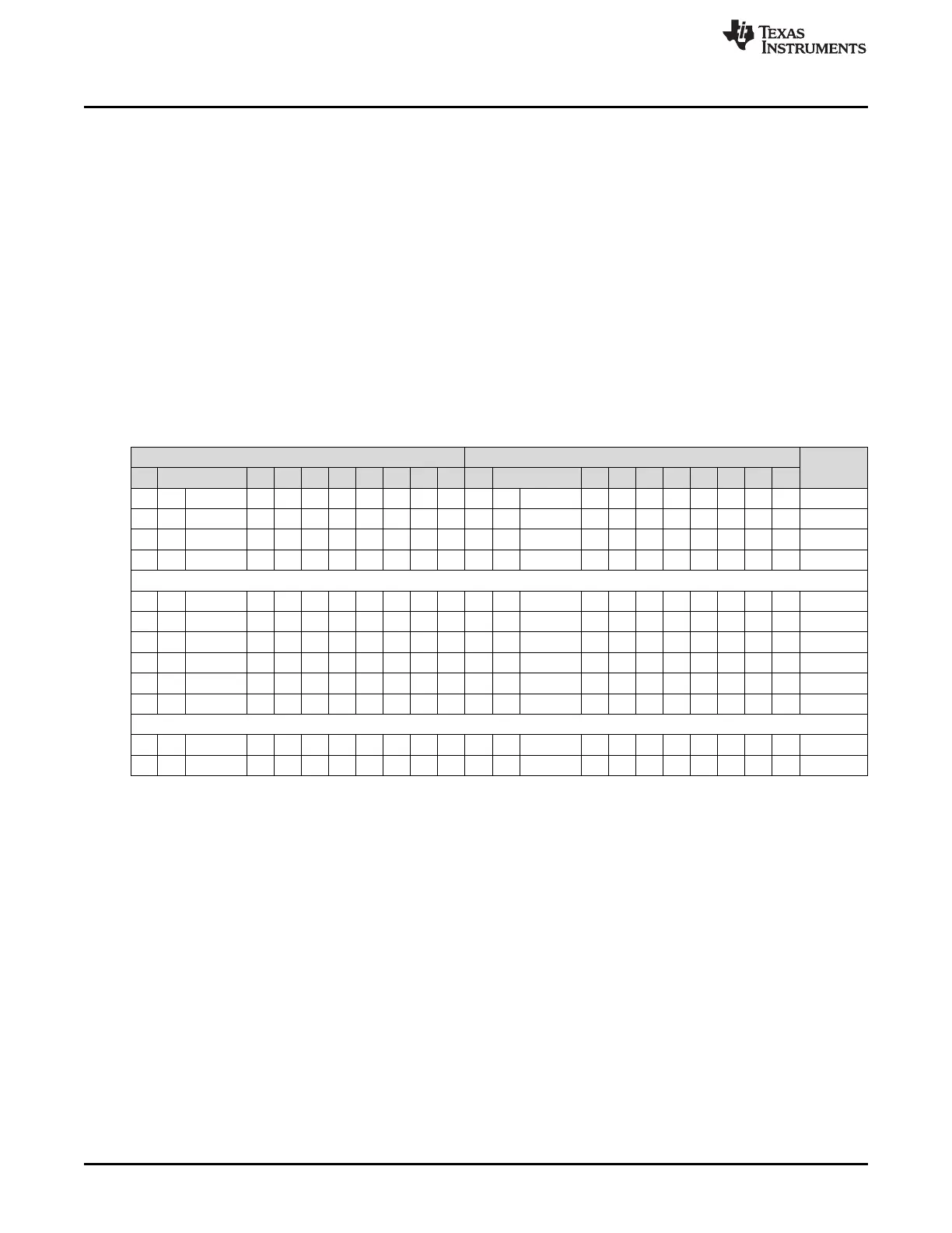
signal being compared. Table 13-2 illustrates the sequence of Compare Mismatch Test. There is no error
signal sent to ESM if the expected errors are seen with each pattern.
Table 13-2. CPU / VIM Compare Mismatch Test Sequence
CPU 1 (Main CPU) Signal Position CPU 2 (Checker CPU) Signal Position
Cycle
n n–1:8 7 6 5 4 3 2 1 0 n n–1:8 7 6 5 4 3 2 1 0
1 1 1s 1 1 1 1 1 1 1 1 1 1 1s 1 1 1 1 1 1 1 0 0
1 1 1s 1 1 1 1 1 1 1 1 1 1 1s 1 1 1 1 1 1 0 1 1
1 1 1s 1 1 1 1 1 1 1 1 1 1 1s 1 1 1 1 1 0 1 1 2
1 1 1s 1 1 1 1 1 1 1 1 1 1 1s 1 1 1 1 0 1 1 1 3
::
1 1 1s 1 1 1 1 1 1 1 1 1 0 1s 1 1 1 1 1 1 1 1 –1
1 1 1s 1 1 1 1 1 1 1 1 0 1 1s 1 1 1 1 1 1 1 1 n
1 1 1s 1 1 1 1 1 1 1 0 1 1 1s 1 1 1 1 1 1 1 1 n+1
1 1 1s 1 1 1 1 1 1 0 1 1 1 1s 1 1 1 1 1 1 1 1 n+2
1 1 1s 1 1 1 1 1 0 1 1 1 1 1s 1 1 1 1 1 1 1 1 n+3
1 1 1s 1 1 1 1 0 1 1 1 1 1 1s 1 1 1 1 1 1 1 1 n+4
::
1 0 1s 1 1 1 1 1 1 1 1 1 1 1s 1 1 1 1 1 1 1 1 2n-1
0 1 1s 1 1 1 1 1 1 1 1 1 1 1s 1 1 1 1 1 1 1 1 2n

 Loading...


