www.ti.com
EMIF Module Architecture
809
SPNU563A–March 2018
Submit Documentation Feedback
Copyright © 2018, Texas Instruments Incorporated
External Memory Interface (EMIF)
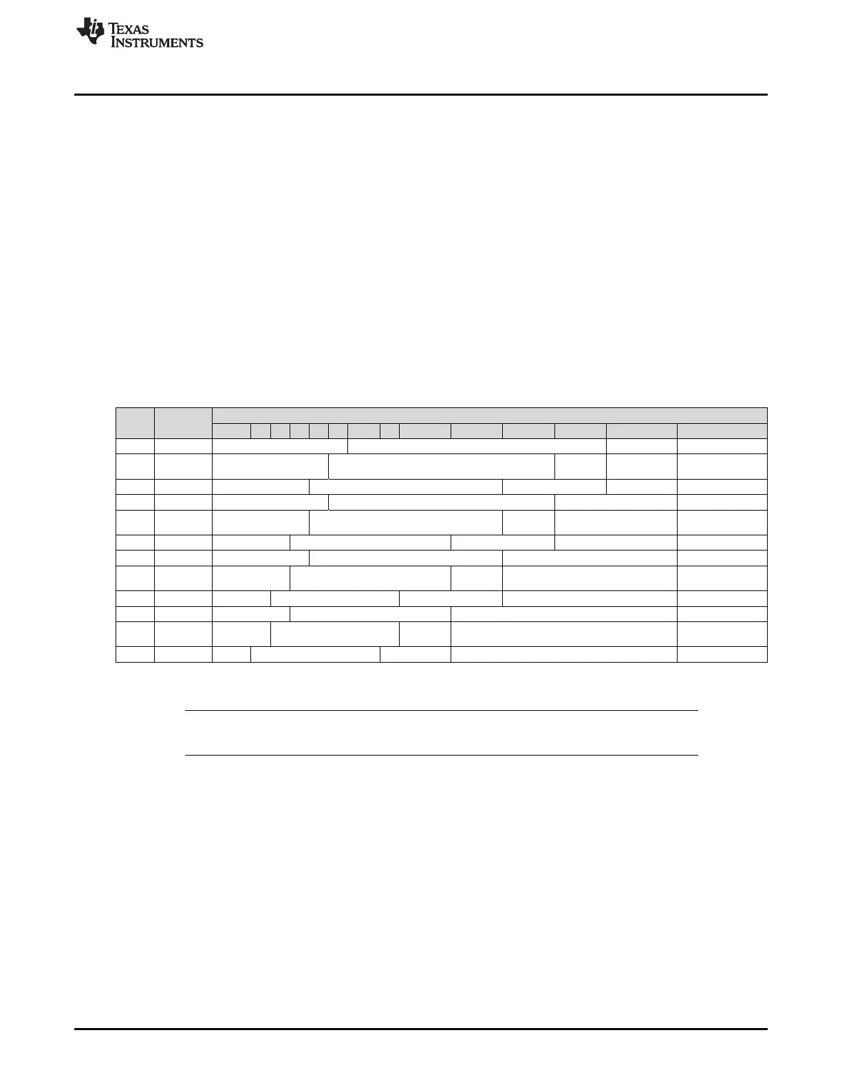
21.2.5.11 Mapping from Logical Address to EMIF Pins
When the EMIF receives an SDRAM access request, it must convert the address of the access into the
appropriate signals to send to the SDRAM device. The details of this address mapping are shown in
Table 21-13 for 16-bit operation. Using the settings of the IBANK and PAGESIZE fields of the SDRAM
configuration register (SDCR), the EMIF determines which bits of the logical address will be mapped to
the SDRAM row, column, and bank addresses.
As the logical address is incremented by one halfword (16-bit operation), the column address is likewise
incremented by one until a page boundary is reached. When the logical address increments across a
page boundary, the EMIF moves into the same page in the next bank of the attached device by
incrementing the bank address EMIF_BA and resetting the column address. The page in the previous
bank is left open until it is necessary to close it. This method of traversal through the SDRAM banks helps
maximize the number of open banks inside of the SDRAM and results in an efficient use of the device.
There is no limitation on the number of banks that can be open at one time, but only one page within a
bank can be open at a time.
The EMIF uses the EMIF_nDQM[1:0] pins during a WRT command to mask out selected bytes or entire
words. The EMIF_nDQM[1:0] pins are always low during a READ command.
Table 21-13. Mapping from Logical Address to EMIF Pins for 16-bit SDRAM
IBANK PAGESIZE
Logical Address
31:27 26 25 24 23 22 21:14 13 12 11 10 9 8:1 0
0 0 - Row Address Col Address EMIF_nDQM[0]
1 0 - Row Address
EMIF_BA[0
]
Col Address EMIF_nDQM[0]
2 0 - Row Address EMIF_BA[1:0] Col Address EMIF_nDQM[0]
0 1 - Row Address Column Address EMIF_nDQM[0]
1 1 - Row Address
EMIF_BA[0
]
Column Address EMIF_nDQM[0]
2 1 - Row Address EMIF_BA[1:0] Column Address EMIF_nDQM[0]
0 2 - Row Address Column Address EMIF_nDQM[0]
1 2 - Row Address
EMIF_BA[0
]
Column Address EMIF_nDQM[0]
2 2 - Row Address EMIF_BA[1:0] Column Address EMIF_nDQM[0]
0 3 - Row Address Column Address EMIF_nDQM[0]
1 3 - Row Address
EMIF_BA[0
]
Column Address EMIF_nDQM[0]
2 3 - Row Address EMIF_BA[1:0] Column Address EMIF_nDQM[0]
NOTE: The upper bit of the Row Address is used only when addressing 256-Mbit and 512-Mbit
SDRAM memories.

 Loading...


