ADC Registers
www.ti.com
898
SPNU563A–March 2018
Submit Documentation Feedback
Copyright © 2018, Texas Instruments Incorporated
Analog To Digital Converter (ADC) Module
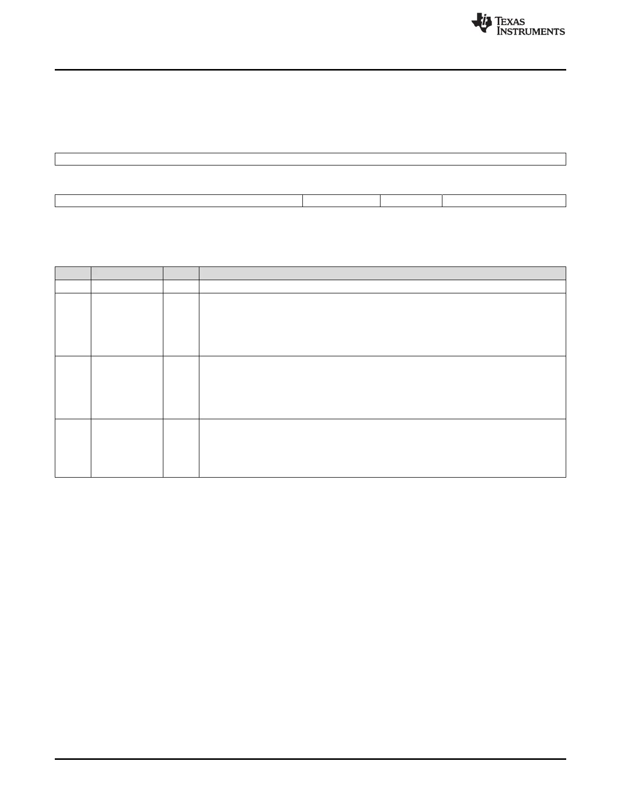
22.3.10 ADC Group2 Trigger Source Select Register (ADG2SRC)
ADC Group2 Trigger Source Select Register (ADG2SRC) is shown in Figure 22-32 and described in
Table 22-16.
Figure 22-32. ADC Group2 Trigger Source Select Register (ADG2SRC) [offset = 24h]
31 8
Reserved
R-0
7 5 4 3 2 0
Reserved G2_EDG_BOTH G2_EDG_SEL G2_SRC
R-0 R/W-0 R/W-0 R/W-0
LEGEND: R/W = Read/Write; R = Read only; -n = value after reset
Table 22-16. ADC Group2 Trigger Source Select Register (ADG2SRC) Field Descriptions
Bit Field Value Description
31-5 Reserved 0 Reads return 0. Writes have no effect.
4 G2_EDG_BOTH Group2 Trigger Edge Polarity Select. This bit configures the group2 to be triggered on both rising
and falling edge detected on the selected trigger source.
Any operation mode read/write:
0 The conversion is triggered only upon detecting an edge defined by the G2_EDG_SEL bit.
1 The conversion is triggered upon detecting either a rising or falling edge.
3 G2_EDG_SEL Group2 Trigger Edge Polarity Select. This bit determines the polarity of the transition on the
selected source that triggers the Group2 conversion.
Any operation mode read/write:
0 A high-to-low transition on the selected source will trigger the Group2 conversion.
1 A low-to-high transition on the selected source will trigger the Group2 conversion.
2-0 G2_SRC Group2 Trigger Source.
Any operation mode read/write:
0-7h The ADC module allows a trigger source to be selected for the Group2 from up to eight options.
These options are device-specific and the device specification must be referred to identify the
actual trigger sources.

 Loading...


