HET[0]
HET[1]
0
0
1
HETXOR0
HETXOR0
N2HET HR 0
N2HET HR 1
www.ti.com
N2HET Functional Description
975
SPNU563A–March 2018
Submit Documentation Feedback
Copyright © 2018, Texas Instruments Incorporated
High-End Timer (N2HET) Module
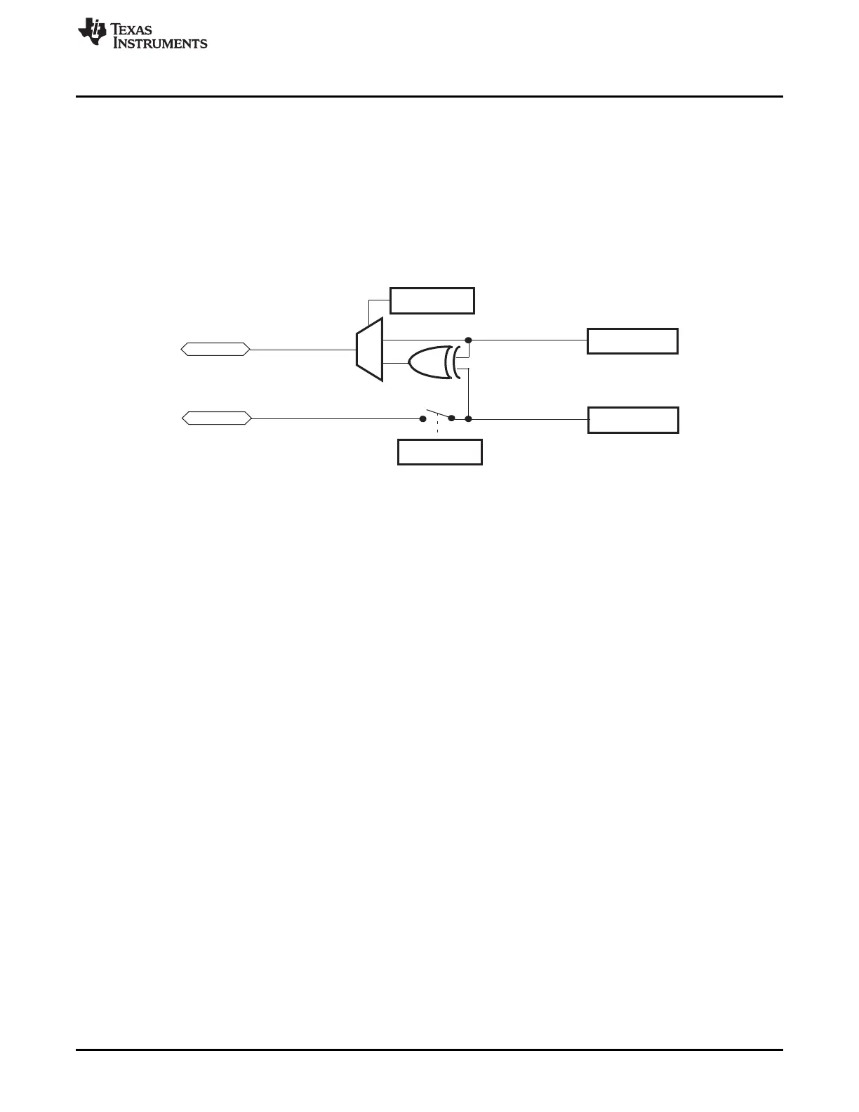
23.2.5.6 AND / XOR-shared HR Structure (Output)
Usually the N2HET design allows only one HR structure to generate HR edges on a pin configured as
output pin. The HETXOR register allows a logical XOR of the output signals of two consecutive HR
structures N (even) and N+1 (odd). See Figure 23-13. In this way, it is possible to generate pulses smaller
than the loop resolution clock since both edges can be generated by two independent HR structures. This
is especially required for symmetrical PWM. See Figure 23-14.
The hardware provides a XOR gate that is connected to the outputs of the HR structure of two
consecutive pins. In this structure, pin N+1 remains available for general-purpose input/output.
Figure 23-13. XOR-shared HR I/O
The following N2HET program gives an example for one channel of the symmetrical PWM. The generated
timing is given in Figure 23-14.
MAXC .equ 22
A_ .equ 0 ; HR structure HR0
B_ .equ 1 ; HR structure HR1
CN CNT { next=EA, reg=A, max=MAXC }
EA ECMP { next=EB, cond_addr=MA, hr_lr=HIGH, en_pin_action=ON, pin=A_,
action=PULSELO, reg=A, data=17, hr_data=115 }
MA MOV32 { next=EB, remote=EA, type=IMTOREG&REM, reg=NONE, data=17, hr_data=19 }
EB ECMP { next=CN, cond_addr=MB, hr_lr=HIGH, en_pin_action=ON, pin=B_,
action=PULSELO, reg=A, data=5, hr_data=13 }
MB MOV32 { next=CN, remote=EB, type=IMTOREG&REM, reg=NONE, data=5, hr_data=13 }
N2HET Settings and output signal calculation for this example program:
• Pin HET[0] and HET[1] are XOR-shared.
• HETPFR[31:0] register = 0x700: lr=128, hr=1, time slots ts = 128
• PWM period (determined by CNT_max field) = (22+1) · LRP = 2944 HRP
• Length of high pulse of (HET[0] XOR HET[1]) =
LH = (17·LRP+115·HRP) - (5·LRP+13 ·HRP)
With lr=128 there is LRP = 128 · HRP, so
LH = (2291 - 653) · HRP = 1638 HRP
• Duty cycle = DC = LH / PWM_period = 1638 HRP / (2944·HRP) = 55.6 %

 Loading...


