element counter
request
2 1
buffer location
U
1Ch
28h
0
34h
U
busy bit
buffer location
U 2 1
U 4Ch 58h
busy bit
0
64h
auto
switch
auto
switch
frame counter
CFTCTB
full address
CFADDRB
buffer full flag
BFINTFL
frame counter
CFTCTA
full address
CFADDRA
Module Operation
www.ti.com
1138
SPNU563A–March 2018
Submit Documentation Feedback
Copyright © 2018, Texas Instruments Incorporated
High-End Timer Transfer Unit (HTU) Module
Figure 24-6 shows a switch at time t1, where buffer 1A is frozen and data stream 1 is directed to buffer
1B, but only after the frame has been completed. It also shows the time (t2 or t3) where 2A is frozen and
data stream 2 is directed to buffer 2B. If the switch happens between the request and the start of the
frame (for example, time t3), then the frame is processed by the new control packet (although the old
control packet was active at the time of the request). The delays between the HTU requests and the start
of the element transfers result from the fact that the HTU can process only one transfer at a time.
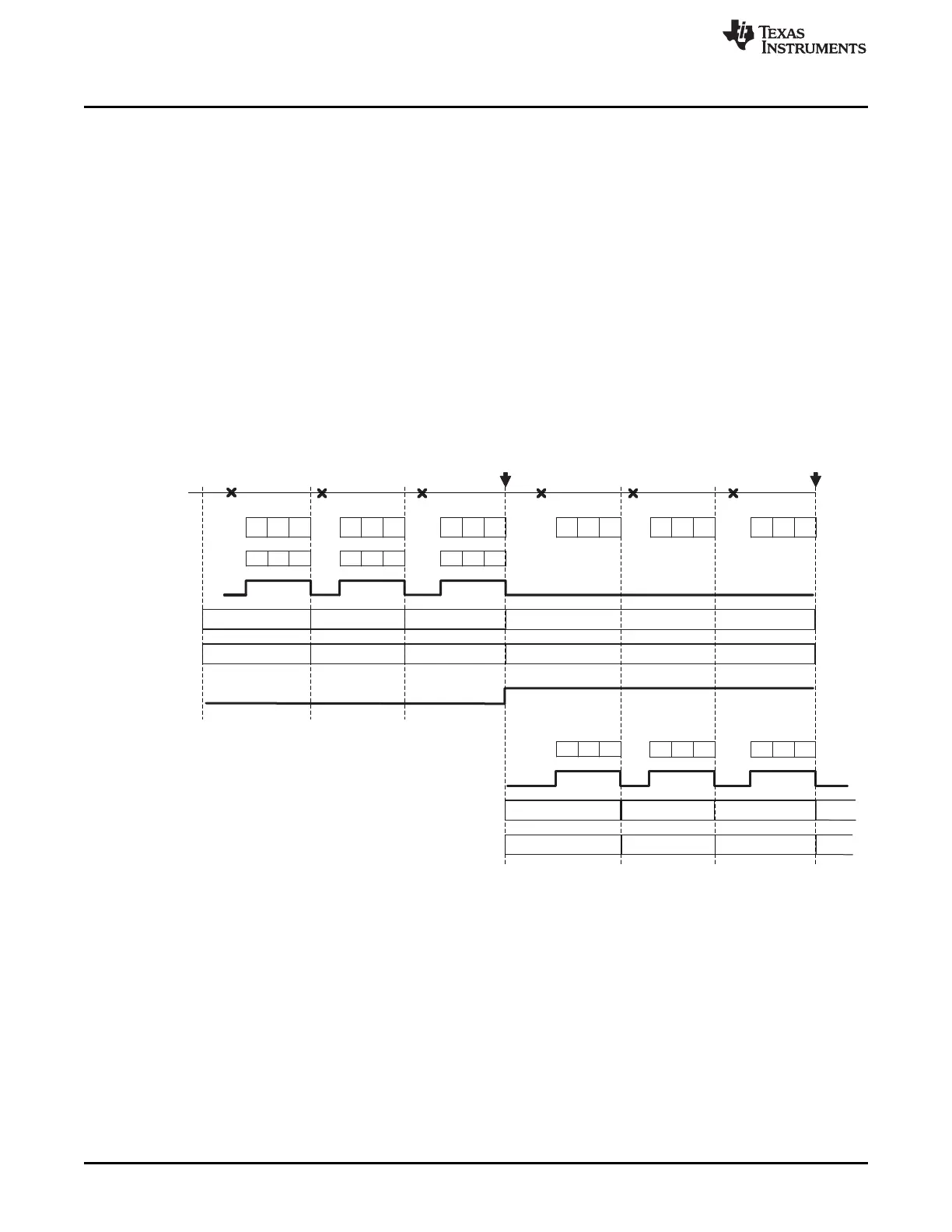
Auto Switch Buffer Mode
If TMBA is set to auto switch mode, then the data stream will continue at the start of buffer B after all
elements of buffer A have been transferred. This means that in the CPENA register, CP A is disabled and
CP B is enabled automatically and buffer B uses its initial main memory address and initial frame counter
to start. The same principle is valid for TMBB and buffer B.
The examples of Figure 24-7 assumes IETCOUNT=3 (Initial Element Transfer Count), IFTCOUNT=3
(Initial Frame Transfer Count, SIZE=0 (Size of Transfer = 32-bit) and ADDFM=0 (Addressing Mode Main
Memory = Post Increment). So there are in total 9 32-bit values in buffer A and B. It also assumes
IFADDRB=10h and IFADDRA=40h. "U" means uninitialized.
Figure 24-7. Timing Example for Auto Switch Buffer Mode

 Loading...


