Message RamData RAM
word x
word x+1
word x+2
word x+3
word x+4
word x+5
word x
word x+1
word x+2
word x+3
word x+4
word x+5
undefined x
undefined x+ 1
undefined x+2
word x
word x+1
word x+2
word x+3
word x+4
word x+5
undefined x
undefined x+ 1
undefined x+2
4 word burst
4 word burst
FTU Transfer
internal E-Ray
Transfer
Input Buffer
Registers
Message RAM Data RAM
word x
word x+1
word x+2
word x+3
word x+4
word x+5
word x+6
word x+7
word x
word x+1
word x+2
word x+3
word x+4
word x+5
undefined x
undefined x+1
undefined x+2
word x
word x+1
word x+2
word x+3
word x+4
word x+5
undefined x
undefined x+1
undefined x+2
4 word burst
FTU Transfer
internal E-Ray
Transfer
Output Buffer
Registers
4 word burst
www.ti.com
Module Operation
1221
SPNU563A–March 2018
Submit Documentation Feedback
Copyright © 2018, Texas Instruments Incorporated
FlexRay Module
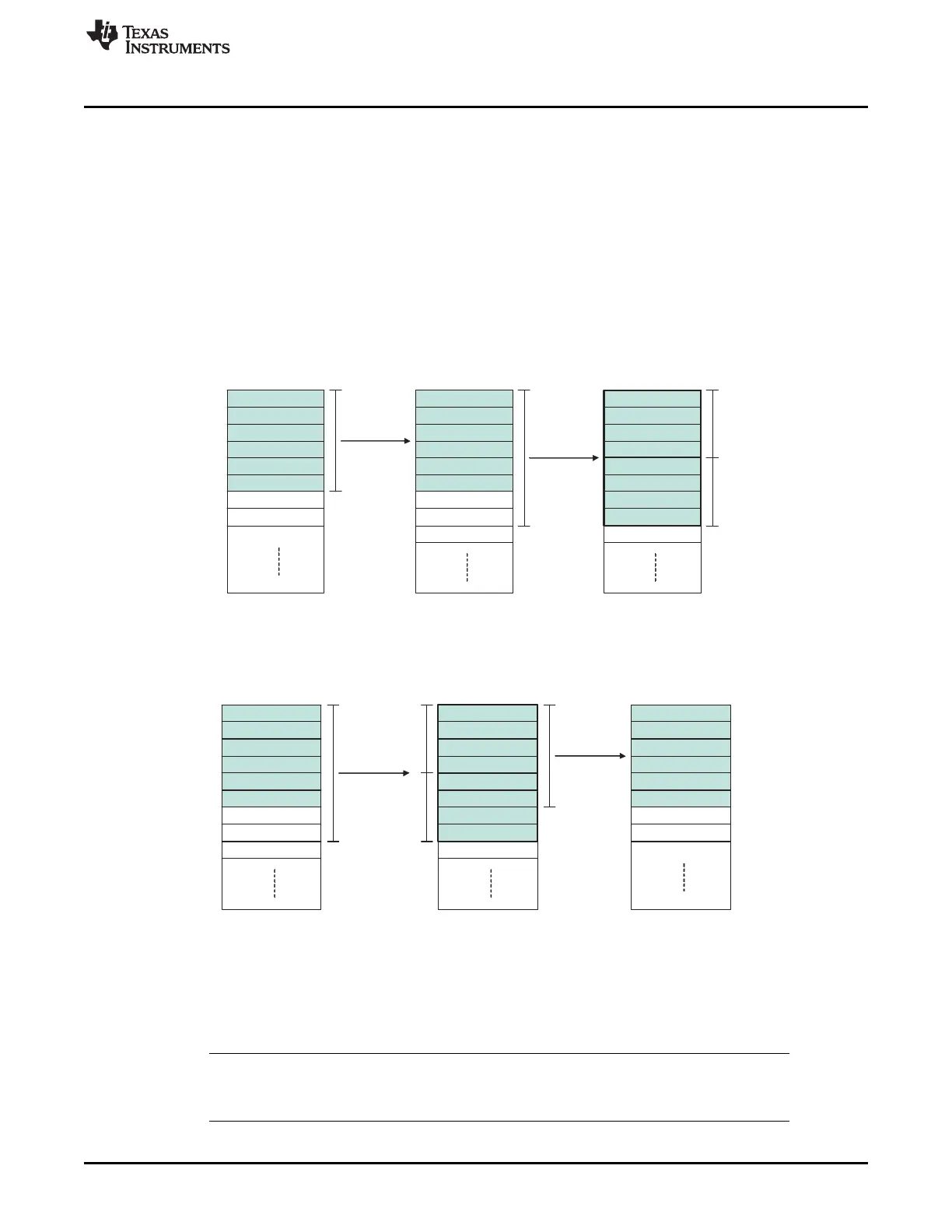
26.2.1.1.1.5 Transfer Size and Types
The data transferred by the Transfer Unit can be selected as:
• data and header section
• header section only
• data section only
The number of transferred payload words is derived from the Payload Length Configured (PLC)
information configured in the Write Header Section 2 (WRHS2) register.
As only 4 word bursts are supported for the Transfer Unit transfers, only multiple of 4x32-bit data packets
are supported. Additional transferred words are undefined, as indicated in Figure 26-7 and Figure 26-8.
Figure 26-7. Example: FTU Read Transfer of 6 Words
Figure 26-8. Example: FTU Write Transfer of 6 Words
Physically the FTU continues reading the additional words from the source location it started the burst
transfer. Therefore, on reads, the additional transferred words depend on the contents of the
Communication Controller Output Buffer Registers as indicated in Figure 26-7. On writes the additional
words depend on the contents of the data RAM, as shown in Figure 26-8. The additional data will be
written to the Communication Controller's Input Buffer Registers, but not transferred to the message RAM.
NOTE: It should be ensured that the allocated data RAM space for FTU transfers ends on 4x32 bit
boundary to avoid possible data overwrites or memory protection issues on FTU reads and
avoid reading the additional data from the source location on FTU writes.

 Loading...


