www.ti.com
FlexRay Module Registers
1323
SPNU563A–March 2018
Submit Documentation Feedback
Copyright © 2018, Texas Instruments Incorporated
FlexRay Module
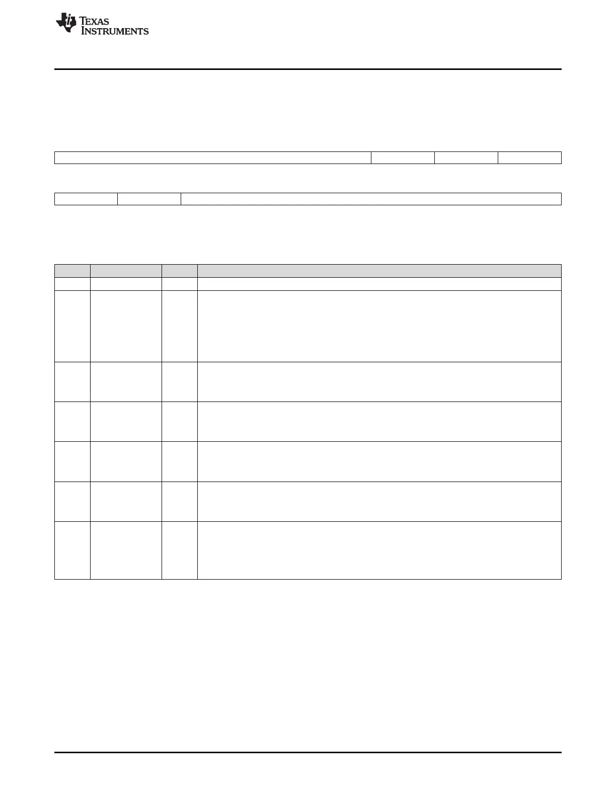
26.3.1.25 Transfer Configuration RAM (TCR)
The TCR consists of 128 entries, each 19 bit wide. The TCR is ECC protected. The ECC protection can
be switched on or off by the 4-bit key (PEL(3-0)) in the Global Control Set/Reset (GCS/R) registers.
Figure 26-106. Transfer Configuration RAM (TCR) [offset_TU_RAM = 0000h - 01FFh]
31 19 18 17 16
Reserved STXR THTSM TPTSM
R-0 R/W-0 R/W-0 R/W-0
15 14 13 0
THTCC TPTCC TSO
R/W-0 R/W-0 R/W-0
LEGEND: R/W = Read/Write; R = Read only; -n = value after reset
Table 26-86. Transfer Configuration RAM (TCR) Field Descriptions
Bit Field Value Description
31-19 Reserved 0 Reads return 0. Writes have no effect.
18 STXR Set Transmit Request.
Control set/reset of buffer transmit requests in the communication controller.
0 Transfer Unit State Machine will set IBCM.STXRH to 0 during a transfer to the communication
controller.
1 Transfer Unit State Machine will set IBCM.STXRH to 1 during a transfer to the communication
controller.
17 THTSM Transfer Header to System Memory.
0 Transfer Unit State Machine will not transfer buffer header to system memory.
1 Transfer Unit State Machine will transfer buffer header to system memory.
16 TPTSM Transfer Payload to System Memory.
0 Transfer Unit State Machine will not transfer buffer payload to system memory.
1 Transfer Unit State Machine will transfer buffer payload to system memory.
15 THTCC Transfer Header to Communication Controller.
0 Transfer Unit State Machine will not transfer buffer header to the communication controller.
1 Transfer Unit State Machine will transfer buffer header to the communication controller.
14 TPTCC Transfer Payload to Communication Controller.
0 Transfer Unit State Machine will not transfer buffer payload to the communication controller.
1 Transfer Unit State Machine will transfer buffer payload to the communication controller.
13-0 TSO Transfer Start Offset.
14-bit buffer address offset in system memory. The resulting address in system memory is
computed by adding the 32-bit aligned buffer address offset (TSO = buffer address offset bits 15:2)
to the base address defined in the TBA register.
Example: A TSO contents of 0x40 results in a Transfer Start Offset of 0x40 × 4 = 0x100

 Loading...


