FlexRay Module Registers
www.ti.com
1358
SPNU563A–March 2018
Submit Documentation Feedback
Copyright © 2018, Texas Instruments Incorporated
FlexRay Module
NOTE: Bits ESWT and SSWT cannot be set to 1 simultaneously. In this case the write access to the
register is ignored, and both bits keep their previous values. Either the external stop watch
trigger or the software stop watch trigger may be used.
The availability of an external stop watch pin is device dependant. Refer to the device data
sheet for details.
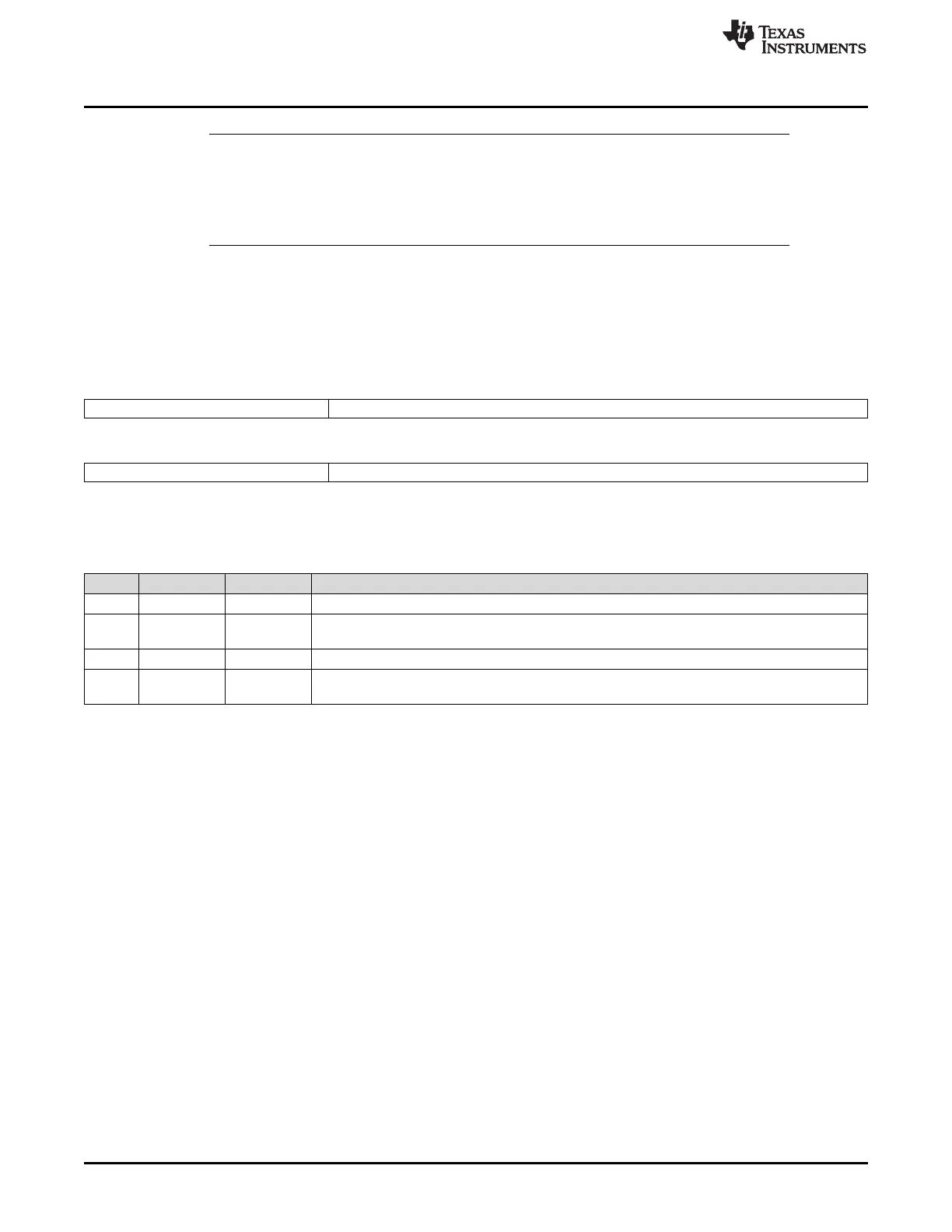
26.3.2.2.11 Stop Watch Register 2 Register (STPW2)
Figure 26-127 and Table 26-106 illustrate this register.
Figure 26-127. Stop Watch Register 2 (STPW2) [offset_CC = 50h]
31 27 26 16
Reserved SSCVB
R-0 R-0
15 11 10 0
Reserved SSCVA
R-0 R-0
LEGEND: R = Read only; -n = value after reset
Table 26-106. Stop Watch Register 2 (STPW2) Field Descriptions
Bit Field Value Description
31-27 Reserved 0 Reads return 0. Writes have no effect.
26-16 SSCVB 0-7FFh Stop watch captured slot counter value channel B. State of the slot counter for channel B when the
stop watch event occurred.
15-11 Reserved 0 Reads return 0. Writes have no effect.
10-0 SSCVA 0-7FFh Stop watch captured slot counter value channel A. State of the slot counter for channel A when the
stop watch event occurred.

 Loading...


