www.ti.com
FlexRay Module Registers
1359
SPNU563A–March 2018
Submit Documentation Feedback
Copyright © 2018, Texas Instruments Incorporated
FlexRay Module
26.3.2.3 Control Registers
This section describes the registers provided by the communication controller to allow the host to control
the operation of the communication controller. The FlexRay protocol specification requires the host to write
application configuration data in CONFIG state only.
NOTE: Be aware that the configuration registers are not locked for writing in DEFAULT_CONFIG
state.
The configuration data is reset when DEFAULT_CONFIG state is entered from hardware reset. To change
POC state from DEFAULT_CONFIG to CONFIG state the host has to apply the controller host interface
command CONFIG. If the host wants the communication controller to leave CONFIG state, the host has to
proceed as described in Lock Register (LCK).
NOTE: All bits marked with an asterisk (*) can be updated in DEFAULT_CONFIG or CONFIG state
only.
26.3.2.3.1 SUC Configuration Register 1 (SUCC1)
The communication controller accepts modifications of the register in DEFAULT_CONFIG or CONFIG
state only.
Figure 26-128 and Table 26-107 illustrate this register.
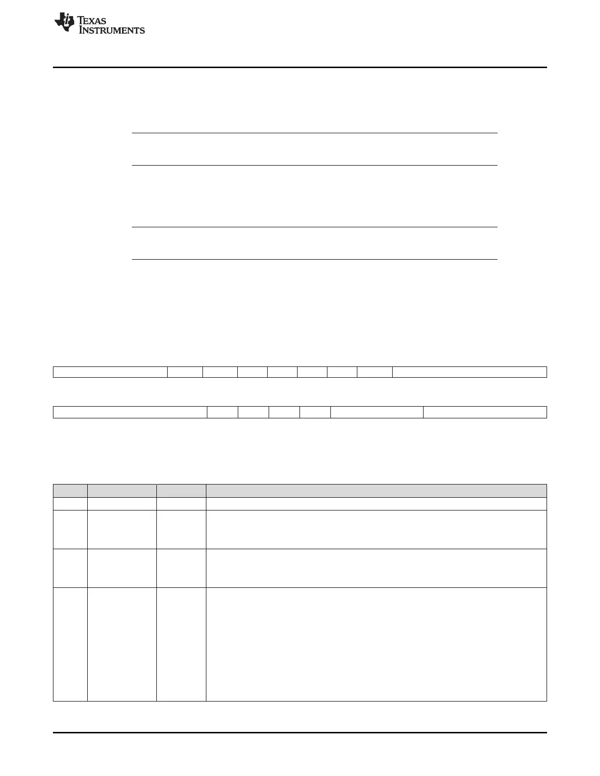
Figure 26-128. SUC Configuration Register 1 (SUCC1) [offset_CC = 80h]
31 28 27 26 25 24 23 22 21 20 16
Reserved CCHB* CCHA* MTSB* MTSA* HCSE* TSM* WUCS* PTA*
R-0 R/W-1 R/W-1 R/W-0 R/W-0 R/W-0 R/W-1 R/W-0 R/W-0
15 11 10 9 8 7 6 4 3 0
CSA* Rsvd TXSY* TXST* PBSY Reserved CMD*
R/W-2h R-0 R/W-0 R/W-0 R-1 R-0 R/W-0
LEGEND: R/W = Read/Write; R = Read only; -n = value after reset; *These bits can be updated in DEFAULT_CONFIG or CONFIG state
only
Table 26-107. SUC Configuration Register 1 (SUCC1) Field Descriptions
Bit Field Value Description
31-28 Reserved 0 Reads return 0. Writes have no effect.
27 CCHB Connected to channel B. Configures whether the node is connected to channel B.
0 Node is not connected to channel B.
1 Node is connected to channel B (default by hardware reset).
26 CCHA Connected to channel A. Configures whether the node is connected to channel A.
0 Node is not connected to channel A.
1 Node is connected to channel A (default by hardware reset).
25 MTSB Select channel B for MTS Transmission. The bit selects channel B for MTS symbol
transmission if requested by writing CMD = 8h. The flag is reset by default and may be modified
only in DEFAULT_CONFIG or CONFIG state.
0 Channel B is not selected for MTS transmission.
1 Channel B is selected for MTS transmission.
Note: MTSB may also be changed outside DEFAULT_CONFIG or CONFIG state when the
write to SUC Configuration Register 1 (SUCC1) is directly preceded by the unlock
sequence for the Configuration Lock Key as described in the Lock Register (LCK). This
may be combined with CHI command SEND_MTS. If both bits MTSA and MTSB are set to
1 an MTS symbol will be transmitted on both channels when requested by writing CMD =
8h.

 Loading...


