www.ti.com
FlexRay Module Registers
1409
SPNU563A–March 2018
Submit Documentation Feedback
Copyright © 2018, Texas Instruments Incorporated
FlexRay Module
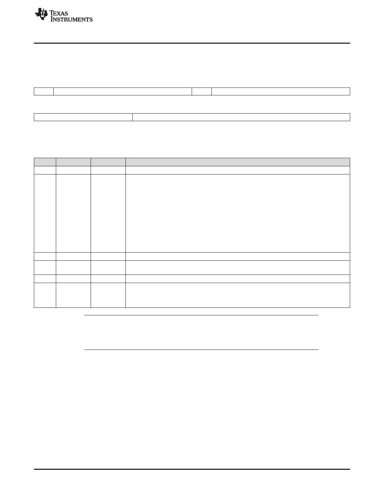
26.3.2.9.3 Read Header Section Register 2 (RDHS2)
Figure 26-188 and Table 26-161 illustrate this register.
Figure 26-188. Read Header Section Register 2 (RDHS2) [offset_CC = 704h]
31 30 24 23 22 16
Rsvd PLR Rsvd PLC
R-0 R-0 R-0 R-0
15 11 10 0
Reserved CRC
R-0 R/W-0
LEGEND: R/W = Read/Write; R = Read only; -n = value after reset
Table 26-161. Read Header Section Register 2 (RDHS2) Field Descriptions
Bit Field Value Description
31 Reserved 0 Reads return 0. Writes have no effect.
30-24 PLR 0-7Fh Payload length received. Payload length value updated from received frame (exception: if
message buffer belongs to the receive FIFO PLR is also updated from received null frames).
When a message is stored into a message buffer the following behavior with respect to payload
length received and payload length configured is implemented:
PLR > PLC:The payload data stored in the message buffer is truncated to the payload length
configured if PLC even or else truncated to PLC + 1.
PLR <= PLC: The received payload data is stored into the message buffers data section. The
remaining data bytes of the data section as configured by PLC are filled with undefined data.
PLR = zero: The message buffers data section is filled with undefined data.
PLC = zero: Message buffer has no data section configured. No data is stored into the message
buffers data section.
23 Reserved 0 Reads return 0. Writes have no effect.
22-16 PLC 0-7Fh Payload length configured. Length of data section (number of 2-byte words) as configured by the
host.
15-11 Reserved 0 Reads return 0. Writes have no effect.
10-0 CRC 0-7FFh Header CRC.
Receive buffer: Header CRC is updated from receive frame.
Transmit buffer: Header CRC is calculated and configured by the host.
NOTE: The Message RAM is organized in 4-byte words. When received data is stored into a
message buffer's data section, the number of 2-byte data words written into the message
buffer is PLC rounded to the next even value. PLC should be configured identical for all
message buffers belonging to the receive FIFO. Header 2 is updated from data frames only.

 Loading...


