www.ti.com
Overview
1499
SPNU563A–March 2018
Submit Documentation Feedback
Copyright © 2018, Texas Instruments Incorporated
Multi-Buffered Serial Peripheral Interface Module (MibSPI) with Parallel Pin
Option (MibSPIP)
– Configurable Parallel modes to use multiple SIMO/SOMI pin
– Configurable number of Chip Selects
In Multi-buffer Mode, in addition to the previous features, many other features are configurable:
– Number of buffers for each peripheral (or data source/destination, up to 256 buffers supported) or
group (up to 8 groupings)
– Number of DMA controlled buffers and number of DMA request channels (up to 8 for each of
transmit and receive)
– Triggers for each groups, trigger types, trigger sources for individual groups(up to 14 external
trigger sources and 1 internal trigger source)
– Number of DMA transfers for each buffer (up to 65536 for up to 8 buffers)
– Un-interrupted DMA buffer transfer (NOBREAK buffer)
NOTE: SIMO - Slave In Master Out Pin
SOMI - Slave Out Master In Pin
SPICS - SPI Chip Select Pin
SPIENA - SPI Enable Pin.
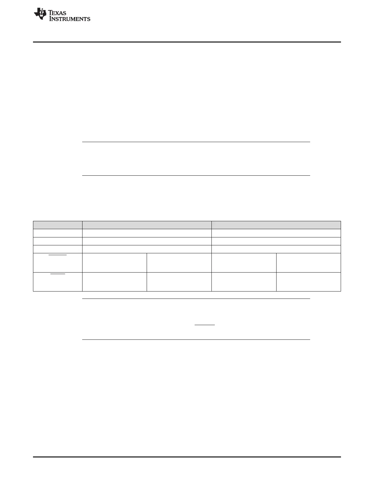
28.1.2 Pin Configurations
The SPI supports data connections as shown in Table 28-1.
Table 28-1. Pin Configurations
Pin Master Mode Slave Mode
SPICLK Drives the clock to external devices Receives the clock from the external master
SPISOMI Receives data from the external slave Sends data to the external master
SPISIMO Transmits data to the external slave Receives data from the external master
SPIENA SPIENA disabled:
GIO
SPIENA enabled:
Receives ENA signal from
the external slave
SPIENA disabled:
GIO
SPIENA enabled:
Drives ENA signal from the
external master
SPICS SPICS disabled:
GIO
SPICS enabled:
Selects one or more slave
devices
SPICS disabled:
GIO
SPICS enabled:
Receives the CS signal
from the external master
NOTE:
1. When the SPICS signals are disabled, the chip-select field in the transmit data is not
used.
2. When the SPIENA signal is disabled, the SPIENA pin is ignored in master mode, and
not driven as part of the SPI transaction in slave mode.

 Loading...


