www.ti.com
Control Registers
1571
SPNU563A–March 2018
Submit Documentation Feedback
Copyright © 2018, Texas Instruments Incorporated
Multi-Buffered Serial Peripheral Interface Module (MibSPI) with Parallel Pin
Option (MibSPIP)
28.3.24 SPI Pin Control Register 9 (SPIPC9)
SPIPC9 only applies to SPI2.
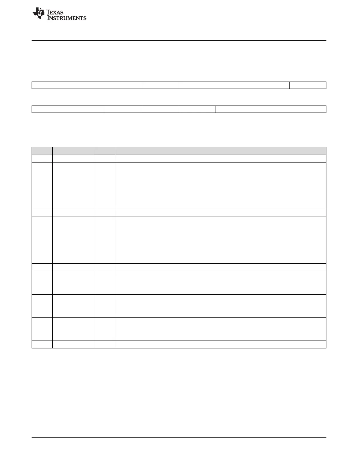
Figure 28-59. SPI Pin Control Register 9 (SPIPC9) [offset = 68h]
31 25 24 23 17 16
Reserved SOMISRS0 Reserved SIMOSRS0
R-0 R/W-0 R-0 R/W-0
15 12 11 10 9 8 0
Reserved SOMISRS0 SIMOSRS0 CLKSRS Reserved
R-0 R/W-0 R/W-0 R/W-0 R-0
LEGEND: R/W = Read/Write; R = Read only; -n = value after reset
Table 28-33. SPI Pin Control Register 9 (SPIPC9) Field Descriptions
Bit Field Value Description
31-25 Reserved 0 Reads return the value that was last written. Writes have no effect.
24 SOMISRS0 SPI2 SOMI[0] slew control. This bit controls between the fast or slow slew mode.
Note: Duplicate Control Bits for SPI2 SOMI[0]. Bit 24 is not physically implemented. It is a
mirror of bit 11. Any write to bit 24 will be reflected on bit 11. When bit 24 and bit 11 are
simultaneously written, the value of bit 11 will control the SPI2 SOMI[0] pin. The read value
of bit 24 always reflects the value of bit 11.
0 Fast mode is enabled; the normal output buffer is used for this pin.
1 Slow mode is enabled; slew rate control is used for this pin.
23-17 Reserved 0 Reads return the value that was last written. Writes have no effect.
16 SIMOSRS0 SPI2 SPISIMO[0] slew control. This bit controls between the fast or slow slew mode.
Note: Duplicate Control Bits for SPI2 SIMO[0]. Bit 16 is not physically implemented. It is a
mirror of bit 10. Any write to bit 16 will be reflected on bit 10. When bit 16 and bit 10 are
simultaneously written, the value of bit 10 will control the SPI2 SOMI[0] pin. The read value
of bit 16 always reflects the value of bit 10.
0 Fast mode is enabled; the normal output buffer is used for this pin.
1 Slow mode is enabled; slew rate control is used for this pin.
15-12 Reserved 0 Reads return 0. Writes have no effect.
11 SOMISRS0 SPI2 SOMI[0] slew control. This bit controls between the fast or slow slew mode.
0 Fast mode is enabled; the normal output buffer is used for this pin.
1 Slow mode is enabled; slew rate control is used for this pin.
10 SIMOSRS0 SPI2 SPISIMO[0] slew control. This bit controls between the fast or slow slew mode.
0 Fast mode is enabled; the normal output buffer is used for this pin.
1 Slow mode is enabled; slew rate control is used for this pin.
9 CLKSRS SPI2 CLK slew control. This bit controls between the fast or slow slew mode.
0 Fast mode is enabled; the normal output buffer is used for this pin.
1 Slow mode is enabled; slew rate control is used for this pin.
8-0 Reserved 0 Reads return the value that was last written. Writes have no effect.
 Loading...


