Control Registers
www.ti.com
1580
SPNU563A–March 2018
Submit Documentation Feedback
Copyright © 2018, Texas Instruments Incorporated
Multi-Buffered Serial Peripheral Interface Module (MibSPI) with Parallel Pin
Option (MibSPIP)
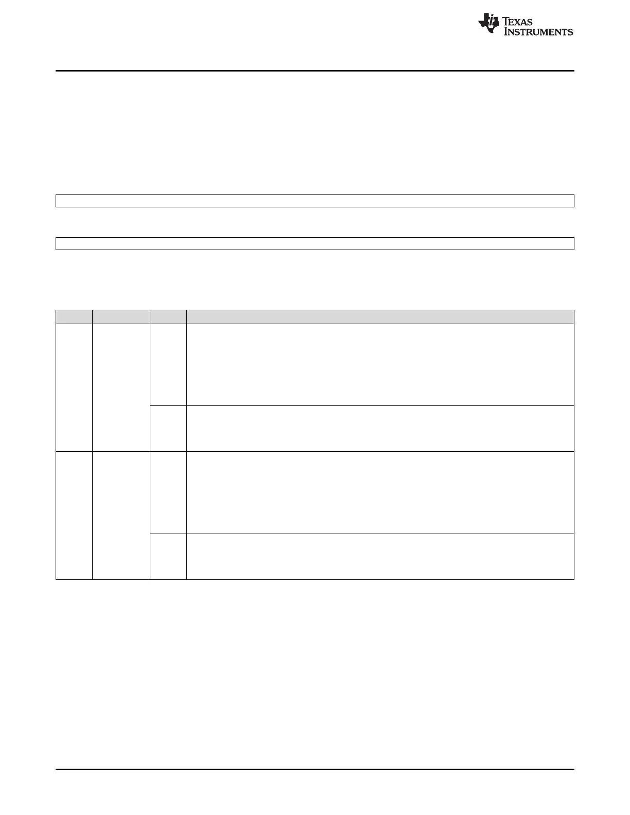
28.3.31 Transfer Group Interrupt Flag Register (TGINTFLAG)
The TGINTFLAG register comprises the transfer group interrupt flags for transfer-completed interrupts
(INTFLGRDYx) and for transfer-suspended interrupts (INTFLGSUSx). Each of the interrupt flags in the
higher half-word and the lower half-word of TGINTFLAG belongs to one TG.
The register map shown in Figure 28-66 and Table 28-40 represents a super-set device with the
maximum number of TGs (16) assumed. The actual number of bits available varies per device.
Figure 28-66. Transfer Group Interrupt Flag Register (TGINTFLAG) [offset = 84h]
31 16
INTFLGRDY[15:0]
R/W1C-0
15 0
INTFLGSUS[15:0]
R/W1C-0
LEGEND: R/W = Read/Write; W1C = Write 1 to clear; -n = value after reset
Table 28-40. Transfer Group Interrupt Level Clear Register (TGITLVCR) Field Descriptions
Bit Field Value Description
31-16 INTFLGRDY[
n]
Transfer-group interrupt flag for a transfer-completed interrupt. Bit 16 corresponds to TG0, bit 17
corresponds to TG1, and so on.
Note: Read Clear Behavior. Reading the interrupt vector registers TGINTVECT0 or TGINTVECT1
automatically clears the interrupt flag bit INTFLGRDYx referenced by the vector number given by
INTVECT0/INTVECT1 bits, if the SUSPEND[0:1] bit in the vector registers is 0.
0 Read: No transfer-completed interrupt occurred since last clearing of the INTFLGRDYx flag.
Write: A write of 0 to this bit has no effect.
1 Read: A transfer finished interrupt from transfer group x occurred. No matter whether the interrupt is
enabled or disabled (INTENRDYx = don't care) or whether the interrupt is mapped to INT0 or INT1,
INTFLGRDYx is set right after the transfer from TGx is finished.
Write: The corresponding bit flag is cleared.
15-0 INTFLGSUS[
n]
Transfer-group interrupt flag for a transfer-suspend interrupt. Bit 0 corresponds to TG0, bit 1
corresponds to TG1, and so on.
Note: Read Clear Behavior. Reading the interrupt vector registers TGINTVECT0 or TGINTVECT1
automatically clears the interrupt flag bit INTFLGSUSx referenced by the vector number given by
INTVECT0/INTVECT1 bits, if the SUSPEND[0:1] bit in the corresponding vector registers is 1.
0 Read: No transfer-suspended interrupt occurred since the last clearing of the INTFLGSUSx flag.
Write: A write of 0 to this bit has no effect.
1 Read: A transfer-suspended interrupt from TGx occurred. No matter whether the interrupt is enabled or
disabled (INTENSUSx = don't care) or whether the interrupt is mapped to INT0 or INT1, INTFLGSUSx
is set right after the transfer from transfer group x is suspended.
Write: The corresponding bit flag is cleared.

 Loading...


