www.ti.com
SCI Control Registers
1745
SPNU563A–March 2018
Submit Documentation Feedback
Copyright © 2018, Texas Instruments Incorporated
Serial Communication Interface (SCI) Module
30.7.7 SCI Flags Register (SCIFLR)
Figure 30-14 and Table 30-10 illustrate this register.
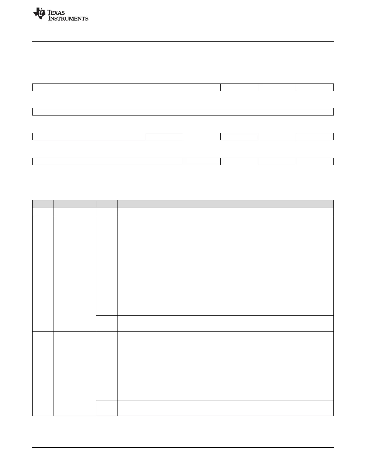
Figure 30-14. SCI Flags Register (SCIFLR) [offset = 1Ch]
31 27 26 25 24
Reserved FE OE PE
R-0 R/W-0 R/W-0 R/W-0
23 16
Reserved
R-0
15 13 12 11 10 9 8
Reserved RX WAKE TX EMPTY TX WAKE RX RDY TX RDY
R-0 R/W-0 R/W-1 R/W-0 R/W-0 R/W-1
7 4 3 2 1 0
Reserved BUSY IDLE WAKE UP BRKDT
R-0 R/W-0 R-0 R/WL-0 R/W-0
LEGEND: R/W = Read/Write; R = Read only; -n = value after reset
Table 30-10. SCI Flags Register (SCIFLR) Field Descriptions
Bit Field Value Description
31-27 Reserved Reads return 0. Writes have no effect.
26 FE Framing error flag. This bit is effective in LIN or SCI-compatible mode. This bit is set when an
expected stop bit is not found. In SCI compatibility mode, only the first stop bit is checked. The
missing stop bit indicates that synchronization with the start bit has been lost and that the character
is incorrectly framed. Detection of a framing error causes the SCI/LIN to generate an error interrupt
if the SET FE INT bit (SCISETINT[26]). The framing error flag is cleared by the following:
• Setting of the SWnRST bit
• Setting of the RESET bit
• A system reset
• Writing a 1 to this bit
• Reading the corresponding interrupt offset in SCIINTVECT0/1
• Reception of a new character/frame, depending on whether the module is in SCI compatible or
LIN mode
In multi-buffer mode the frame is defined in the SCIFORMAT register.
0 Read: No framing error has been detected since the last clear.
Write: No effect.
1 Read: A framing error has been detected since the last clear.
Write: The bit is cleared to 0.
25 OE Overrun error flag. This bit is set when the transfer of data from SCIRXSHF to SCIRD overwrites
unread data already in SCIRD. Detection of an overrun error causes the LIN to generate an error
interrupt if the SET OE INT bit (SCISETINT[25]) is set. The OE flag is reset by the following:
• Setting of the SWnRST bit
• Setting of the RESET bit
• A system reset
• Writing a 1 to this bit
• Reading the corresponding interrupt offset in SCIINTVECT0/1
0 Read: No overrun error has been detected since the last clear.
Write: No effect.
1 Read: An overrun error has been detected since the last clear.
Write: The bit is cleared to 0.

 Loading...


